My understanding of the CORDIC (Co-ordinate Rotation by DIgital Computer) thanks to the nice article in [DSPGURU-CORDIC].
Bit Error Rate (BER) for BPSK modulation
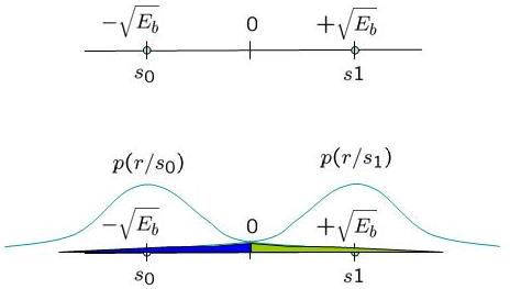
In this post, we will derive the theoretical equation for bit error rate (BER) with Binary Phase Shift Keying (BPSK) modulation scheme in Additive White Gaussian Noise (AWGN) channel. The BER results obtained using Matlab/Octave & Python simulation scripts show good agreement with the derived theoretical results.
System Model
Transmitter
With Binary Phase Shift Keying (BPSK), the binary digits 1 and 0 maybe represented by the analog levels and
respectively. The system model is as shown in the Figure below.
Straight line fit using least squares estimate
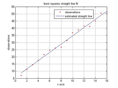
Two points suffice for drawing a straight line. However we may be presented with a set of data points (more than two?) presumably forming a straight line. How can one use the available set of data points to draw a straight line?
A probable approach is to draw a straight line which hopefully minimizes the error between the observed data points and estimated straight line.
where
is the observed data points and
is the points from estimated straight line.
Continue reading “Straight line fit using least squares estimate”
Example of Cascaded Integrator Comb filter in Matlab
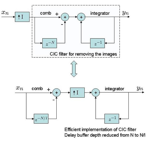
Equivalence of Moving Average and CIC filter
Let me briefly share my understanding on the cascaded integrator comb (CIC) filter, thanks to the nice article. For understanding the cascaded integrator comb (CIC) filter, firstly let us understand the moving average filter, which is accumulation latest samples of an input sequence
.
Continue reading “Example of Cascaded Integrator Comb filter in Matlab”
Interpreting the output of fft() operation in Matlab
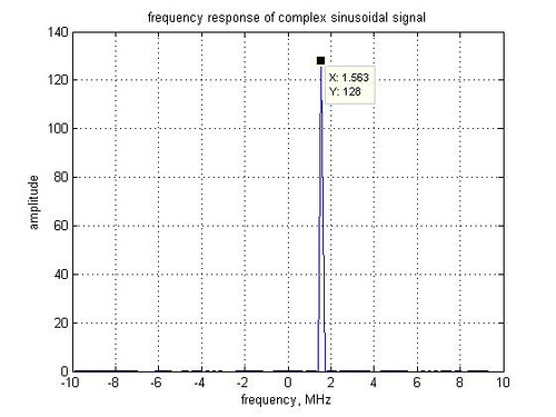
It might be interesting to interpret the output of the fft() function in Matlab. Consider the following simple examples.
fsMHz = 20; % sampling frequency
fcMHz = 1.5625; % signal frequency
N = 128; % fft size
% generating the time domain signal
x1T = exp(j*2*pi*fcMHz*[0:N-1]/fsMHz);
x1F = fft(x1T,N); % 128 pt FFT
figure;
plot([-N/2:N/2-1]*fsMHz/N,fftshift(abs(x1F))) ; % sub-carriers from [-128:127]
xlabel('frequency, MHz')
ylabel('amplitude')
title('frequency response of complex sinusoidal signal');
Continue reading “Interpreting the output of fft() operation in Matlab”
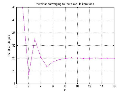
First order digital PLL for tracking constant phase offset
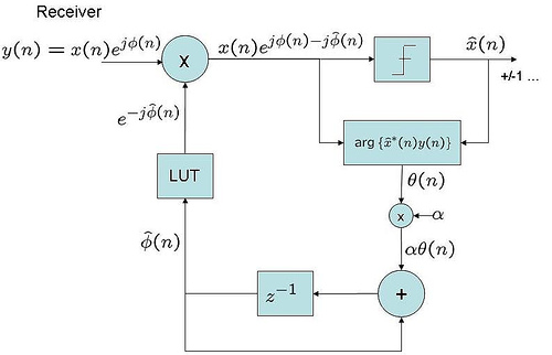
Considering a typical scenario where there might exist a small phase offset between local oscillator between the transmitter and receiver.
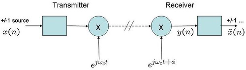
Figure 1 : Transmitter receiver with constant phase offset
In such cases, it might be desirable to estimate and track the phase offset such that the performance of the receiver does not degrade.
Continue reading “First order digital PLL for tracking constant phase offset”
Polyphase filters for interpolation
In typical digital signal processing applications, there arises need to increase the sampling frequency of a signal sequence, where the higher sampling frequency is an integer multiple of the original sampling frequency i.e for a signal sequence with a sampling frequency
, change the sampling frequency to
, where
is an integer.
Using Toeplitz matrices in MATLAB
The definition of Toeplitz matrix from [1] is:
A matrix is said to be Toeplitz if the elements
are determined completely by the difference
.
2nd order sigma delta modulator
In a previous post, the variance of the in-band quantization noise for a first order sigma delta modulator was derived. Taking it one step furhter, let us find the variance of the quantization noise filtered by a second order filter.
With a first order filter, the quantization noise passes through a system with transfer function (Refer Eq. 9.2.17 in [1]). The frequency response of
is
(Refer Eq. 9.2.18 in [1]).
Sigma delta modulation
In an earlier post, it was mentioned that delta modulator without the quantizer is identical to convolving an input sequence with . Let us first try to validate that thought using a small MATLAB example and using the delta modulator circuit shown in Figure 9.13a of DSP-Proakis [1].
% delta modulation
xn = sin(2*pi*1/64*[0:63]);
xhatn = 0;

for ii = 1:length(xn)

dn = xn(ii) - xhatn;
dqn = dn; % no quantizing done, when quantizing is done: dqn = 2*(dn>0) - 1;
xqn = dqn + xhatn;

% dump of transmitter variables
dnDump(ii) = dn;
dqnDump(ii) = dqn;
xqnDump(ii) = xqn;
xhatnDump(ii) = xhatn;

xhatn = xqn; %  variable storing one-sample delayed version of xn

% receiver
rn = rn + dqn;
rnDump(ii) = rn;

end


% implementation by convolving with [1 -1]

d1n = conv(xn,[1 -1]);
diff = (dnDump - d1n(1:64))
Zero-order hold and first-order hold based interpolation
In problem 9.14 of DSP-Proakis, the objective is to analyze the effect of zero-order interpolation and first-order interpolation to double the number of samples in the sinusoidal
while keeping the sampling frequency unchanged.
My take:
The first part of the problem (a) is to generate the sequence having half the frequency of
. For zero-order interpolation, the interpolated samples can be generated by holding the current sample till the new sampling instant (Ref: Section 9.3.1 -Sample and Hold [1]). The impulse response of such a system is a rectangular function.
Continue reading “Zero-order hold and first-order hold based interpolation”
Signal to quantization noise in quantized sinusoidal
In problem 4.37 of DSP-Proakis [1], the task is to analyze the total harmonic distortion in quantized sinusoidal, where
.
Continue reading “Signal to quantization noise in quantized sinusoidal”
Harmonic distortion in digital sinusoidal generators
In Problem 4.36 of DSP-Proakis [1], the task is to provide insights into harmonic distortion which may be present in practical sinusoidal generators. Consider the signal
, where
.
My take:
The discrete time signal of fundamental period can consist of frequency components separated by
radians or
cycles (Refer Section4.2 in [1]).
The Fourier series coefficient at frequency is,
.
The total power of the signal over a period is same as the sum of the power of all the Fourier series coefficients (harmonic components) i.e.
.
Continue reading “Harmonic distortion in digital sinusoidal generators”
LaTex on blogger not working?
I noticed that the scripts provided from http://wolverinex02.googlepages.com/emoticonsforblogger2 for writing equations on blogger stopped working.
Reason:
The address of the public mimeTEX server is changed to /cgi-bin/mimetex.cgi? from Thursday, March15 2007.