BER for BPSK in ISI channel with Zero Forcing equalization

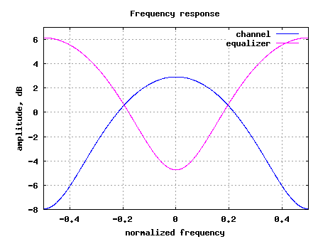
In the past, we had discussed BER for BPSK in flat fading Rayleigh channel. In this post, lets discuss a frequency selective channel with the use of Zero Forcing (ZF) equalization to compensate for the inter symbol interference (ISI). For simplifying the discussion, we will assume that there is no pulse shaping at the transmitter. The ISI channel is assumed to be a fixed 3 tap channel.

Continue reading “BER for BPSK in ISI channel with Zero Forcing equalization”

Eye diagram with raised cosine filtering

We have discussed about probable transmit pulse shaping filter and have observed that raised cosine filtering filtering allows a simpler implementation, albeit at the cost of increased bandwidth. Let us know understand the eye diagram, which is a useful graphical tool to quantify the degradation of the signal due to filtering.

Eye diagram

An eye diagram is generated in an oscilloscope operating in the persistence mode by observing the output of the filter with the symbol timing serving as the trigger. The observation window can be set as 2 times the symbol period. (Refer. Section 5.1.3 in [DIG-COMM-BARRY-LEE-MESSERSCHMITT]).

Continue reading “Eye diagram with raised cosine filtering”

Raised cosine filter for transmit pulse shaping

In the previous post on transmit filtering using Nyquist pulse, we had briefly learned that the information symbol with a symbol period can be transmitted without inter symbol interference (ISI) by using Nyquist pulse,

.

The resultant waveform is ideally bandlimited to frequencies from Hz to Hz.

However, in typical transmission schemes, we do not hear of pulse shaping using sinc() filters. Rather, pulse shaping using raised cosine filter is frequently used. In this post, objective is to understand the motivation behind using raised cosine filtering for pulse shaping.

Continue reading “Raised cosine filter for transmit pulse shaping”

Transmit pulse shaping filter – rectangular and sinc (Nyquist)

In the previous post on I-Q modulator and de-modulator, we had briefly mentioned that the a baseband PAM transmission can be modelled as

, where

is the symbol period,

is the symbol to transmit,

is the transmit filter,

is the symbol index and

is the output waveform.

In this post, the objective is to understand the properties of the transmit filter i.e. to find out a filter which occupies the minimum required bandwidth while ensuring inter-symbol-interference (ISI) free transmission of the information symbol .

Continue reading “Transmit pulse shaping filter – rectangular and sinc (Nyquist)”

Digital implementation of RC low pass filter

Thanks to the nice article from Xilinx TechXclusives [XLNX-TECH], let us try to understand the probable digital implementation of resistor-capacitor based low pass filter. Consider a simple RC filter shown in the figure below. Assuming that there is no load across the capacitor, the capacitor charges and discharges through the resistor path.

RC low pass filter

Figure: RC low pass filter

Continue reading “Digital implementation of RC low pass filter”

Example of Cascaded Integrator Comb filter in Matlab

Equivalence of Moving Average and CIC filter

Let me briefly share my understanding on the cascaded integrator comb (CIC) filter, thanks to the nice article. For understanding the cascaded integrator comb (CIC) filter, firstly let us understand the moving average filter, which is accumulation latest samples of an input sequence .

Continue reading “Example of Cascaded Integrator Comb filter in Matlab”

Polyphase filters for interpolation

In typical digital signal processing applications, there arises need to increase the sampling frequency of a signal sequence, where the higher sampling frequency is an integer multiple of the original sampling frequency i.e for a signal sequence with a sampling frequency , change the sampling frequency to , where is an integer.

Continue reading “Polyphase filters for interpolation”

Zero-order hold and first-order hold based interpolation

In problem 9.14 of DSP-Proakis, the objective is to analyze the effect of zero-order interpolation and first-order interpolation to double the number of samples in the sinusoidal

while keeping the sampling frequency unchanged.

My take:

The first part of the problem (a) is to generate the sequence having half the frequency of . For zero-order interpolation, the interpolated samples can be generated by holding the current sample till the new sampling instant (Ref: Section 9.3.1 -Sample and Hold [1]). The impulse response of such a system is a rectangular function.

Continue reading “Zero-order hold and first-order hold based interpolation”