Binary to Gray code conversion for PSK and PAM

In this post, let us try to understand Gray codes and their usage in digital communication. Quoting from Wiki entry on Gray code [Gray-Wiki],

The reflected binary code, also known as Gray code after Frank Gray, is a binary numeral system where two successive values differ in only one digit.

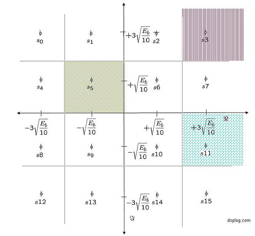
In a digital communication system, if the constellation symbols are Gray encoded, then the bit pattern representing the adjacent constellation symbols differ by only one bit. We will show in another post that having this encoding structure gives a lesser probability of error than the ‘natural binary ordering’. However, in this post, let us try to figure out the conversion of natural binary representation to Gray code. Continue reading “Binary to Gray code conversion for PSK and PAM”

Comparing 16PSK vs 16QAM for symbol error rate

In two previous posts, we have derived theoretical symbol error rate for 16-QAM and 16-PSK modulation schemes. The links are:

(a) Symbol error rate for 16-PSK

(b) Symbol error rate for 16-QAM

Given that we are transmitting the same number of constellation points in both 16-PSK and 16-QAM, let us try to understand the better modulation scheme among the two, i.e. to answer the following question:

For the same signal to noise ratio , will 16-PSK or 16-QAM give a lower symbol error rate?

Continue reading “Comparing 16PSK vs 16QAM for symbol error rate”

Simulating Minimum Shift Keying Transmitter

Minimum shift keying (MSK) is an important concept to learn in digital communications. It is a form of continuous phase frequency shift keying . In minimum phase shift keying, two key concepts are used.

(a) The frequency separation of the sinusoidals used for representing bits 1’s and 0’s are , where is the symbol period.

(b) It is ensured that the resulting waveform is phase continuous.

Motivation of continuous phase

In a previous post (here), we have understood that the minimum frequency separation for two sinusoidals having zero phase difference to be orthogonal is , where is the symbol period. However, it can be observed that at each symbol boundary, there is a phase discontinuity. The presence of phase discontinuities can result in large spectral side lobes outside the desired bandwidth. Hence the need for having a frequency modulated signal which is phase continuous.
Continue reading “Simulating Minimum Shift Keying Transmitter”

Symbol Error Rate (SER) for 16-QAM

Given that we have went over the symbol error probability for 4-PAM and symbol error rate for 4-QAM , let us extend the understanding to find the symbol error probability for 16-QAM (16 Quadrature Amplitude Modulation). Consider a typical 16-QAM modulation scheme where the alphabets (Refer example 5-37 in [DIG-COMM-BARRY-LEE-MESSERSCHMITT]).

are used.

Continue reading “Symbol Error Rate (SER) for 16-QAM”

Symbol Error Rate (SER) for QPSK (4-QAM) modulation

Given that we have discussed symbol error rate probability for a 4-PAM modulation, let us know focus on finding the symbol error probability for a QPSK (4-QAM) modulation scheme.

Background

Consider that the alphabets used for a QPSK (4-QAM) is (Refer example 5-35 in [DIG-COMM-BARRY-LEE-MESSERSCHMITT]).


Continue reading “Symbol Error Rate (SER) for QPSK (4-QAM) modulation”

Symbol Error Rate (SER) for 4-PAM

Following discussion of bit error rate (BER) for BPSK and bit error rate for FSK, it may be interesting to move on to discuss a higher order constellation such as Pulse Amplitude Modulation (PAM).

Consider that the alphabets used for a 4-PAM is (Refer example 5-34 in [DIG-COMM-BARRY-LEE-MESSERSCHMITT]).

Continue reading “Symbol Error Rate (SER) for 4-PAM”

Coherent demodulation of DBPSK

In a previous post, we discussed about a probable first order digital PLL for tracking constant phase offset. The assumption was that as the phase offset is small and the bits gets decoded correctly, the phase difference between the ideal and actual constellation gives the initial value of phase. However, in typical scenarios it may be possible that the above assumption may not be valid, resulting in phase ambiguity.

Continue reading “Coherent demodulation of DBPSK”

Scaling factor in QAM

When QAM (Quadrature Amplitude Modulation) is used, typically one may find a scaling factor associated with the constellation mapping operation. It may be reasonably obvious that this scaling factor is for normalizing the average energy to one.

This post attempts to compute the average energy of the 16-QAM, 64-QAM and M-QAM constellation (where is a power of 2), thanks to the nice example 5.16 in [DIG-COMM-BARRY-LEE-MESSERSCHMITT].

Consider a typical 16-QAM modulation scheme where the alphabets

are used.

Continue reading “Scaling factor in QAM”

Bit Error Rate (BER) for frequency shift keying with coherent demodulation

Following the request by Siti Naimah, this post discuss the bit error probability for coherent demodulation of binary Frequency Shift Keying (BFSK) along with a small Matlab code snippet.

Using the definition provided in Sec 4.4.4 of [DIG-COMM-SKLAR]), in binary Frequency shift keying (BFSK), the bits 0’s and 1’s are represented by signals and having frequencies and respectively, i.e.

,

where

is the energy ,

is the symbol duration and

is an arbitrary phase (assume to be zero).

Continue reading “Bit Error Rate (BER) for frequency shift keying with coherent demodulation”

Bit Error Rate (BER) for BPSK modulation

In this post, we will derive the theoretical equation for bit error rate (BER) with Binary Phase Shift Keying (BPSK) modulation scheme in Additive White Gaussian Noise (AWGN) channel. The BER results obtained using Matlab/Octave & Python simulation scripts show good agreement with the derived theoretical results.

System Model

Transmitter

With Binary Phase Shift Keying (BPSK), the binary digits 1 and 0 maybe represented by the analog levels and respectively. The system model is as shown in the Figure below.

Continue reading “Bit Error Rate (BER) for BPSK modulation”