Question 16 on electromagnetics from GATE (Graduate Aptitude Test in Engineering) 2012 Electronics and Communication Engineering paper.
Q16. A coaxial cable with an inner diameter of 1mm and outer diameter of 2.4mm is filled with a dielectric of relative permittivity 10.89. Given  , the characteristic impedance of the cable is
(A) 
(B) 
(C) 
(D) 

Solution
To answer this question, am referring to the discussion on capacitance per unit length (Section 1.9) , inductance per unit length (Section 2.4) and characteristic impedance (Section 5.2) of a coaxial cable from Fields and Waves in Communication Electronics, Simon Ramo, John R. Whinnery, Theodore Van Duzer (buy from Amazon.com , buy from Flipkart.com).
Finding the capacitance per unit length:
Using Gauss law :
For a closed Gaussian surface  , the electrical flux is given by :
 , where
 is the electrical flux,
 is the electric field,
 is the vector representing the infinitesimal area on the surface ,
 is the net charge enclosed by the surface and
 is the permittivity of vacuum.
Let us use this result to find the electrical field in a coaxial cable formed by two conducting cylinders of radii  and
and  respectively with a dielectric
  between them (shown in the figure below).

Figure : Coaxial cable showing the imaginary Gaussian surface (cylinder with radius  and length
  )
)
For finding the electric field in region  , assume a cylindrical Gaussian surface of radius and length (as shown by the dashed line).
Applying Gauss law,
 ,
,
where
 is the charge per unit length,
total charge enclosed is the charge per unit length multiplied by the length i.e.  and
and
 is the permittivity ( is the permittivity of vacuum,
  is the permittivity of the material).
Given that the electrical field is is parallel to the surface and is uniform across the Gaussian surface, it can be moved out of the integral, i.e
 .
.
The term  is the surface area of the cylinder with radius of length and is,
 .
.
Substituting, the electric field in the region is,
 .
.
With the above electric field, the potential difference between the coaxial cylinders is computed as,
\end{array}) .
.
The capacitance between two electrodes is defined as the charge  on each electrode per volt of potential difference
  between then,
 .
.
Assuming that the field is only radial and the total charge per unit length is , the capacitance per unit length is
},&\mbox{ F/m}\end{aray}}) .
.
Finding the inductance per unit length:
Using Ampere’s Law :
The total current  inside a closed curve
  is the line integral of the magnetic field
  (in Tesla)
 ,
,
where
is the magnetic field (in Tesla)
 is the vector representing the infinitesimal line on the closed loop ,
is the net current enclosed by the closed loop and
 is the permeability of vacuum.
Let us use this result to find the magnetic field in a coaxial cable formed by two conducting cylinders of radii and respectively with a dielectric having permeability of  between them (shown in the figure below).

Figure : Coaxial cable showing the imaginary Amperian loop (circle with radius )
Applying Ampere’s law,
 ,
,
where
 is the permeability ( is the permeability of vacuum.
  is the permeability of the material).
Given that the magnetic field is is parallel to the line and is uniform across the closed loop, it can be moved out of the integral, i.e
 .
.
The term  is the circumference of the circle with radius and is,
  .
.
Substituting, the magnetic field in the region is,
 .
.
The inductance is defined as ratio of magnetic field over a surface and the the current.
 .
.
For a unit length, the integral of magnetic field in the region is,
\end{array}) .
.
Substituting, the inductance per unit length is,
&\mbox{ H/m}\end{array}) .
.
Note :
YouTube videos uploaded by user lasseviren1 aided me in understanding the integrals in electric field and magnetic field. Do checkout the play-lists : Gauss’s Law , Sources of Magnetic Fields
The characteristic impedance :
From wiki entry on characteristic impedance, the general expression for the characteristic impedance of a transmission line is
 ,
,
where,
 is the resistance per unit length,
 is the inductance per unit length,
is the capacitance per unit length,
 is the conductance per unit length and
 is the angular frequency.
Assuming a loss less transmission line, i.e.  , the equation reduces to,
 .
.
Substituting the expressions for inductance per unit length and capacitance per unit length for a coaxial cable,
}{2\pi}\end{array}}) .
.
Substituting the numbers from the problem at hand,


 ,
,
the characteristic impedance is,
 .
.
The calculated choice is not listed in the options. However if we ignore the  term, the calculated number comes to around
  . That does not help, does it? 🙂
References
[1] GATE Examination Question Papers [Previous Years] from Indian Institute of Technology, Madras http://gate.iitm.ac.in/gateqps/2012/ec.pdf
[2] Fields and Waves in Communication Electronics, Simon Ramo, John R. Whinnery, Theodore Van Duzer (buy from Amazon.com, buy from Flipkart.com).
[3] The youtube videos uploaded by user lasseviren1 aided me in understanding the integrals in electric field and magnetic field. Do checkout the play-lists : Gauss’s Law
Sources of Magnetic Fields
[4] Characteristic impedance
[5] Ampere’s Law
[6] Gauss law
[7] Permeability
[8] Permittivity
[9] Electrical Flux
}) for positive frequencies is shown below. The values of
for positive frequencies is shown below. The values of \]}) and
and \]\|}) , respectively are
, respectively are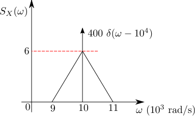


})
})