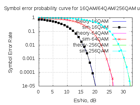
In May 2008, we derived the theoretical symbol error rate for a general M-QAM modulation (in Embedded.com, DSPDesignLine.com and dsplog.com) under Additive White Gaussian Noise. While re-reading that post, felt that the article is nice and warrants a re-run, using OFDM as the underlying physical layer. This post discuss the derivation of symbol error rate for a general M-QAM modulation. The companion Matlab script compares the theoretical and the simulated symbol error rate for 16QAM, 64QAM and 256QAM over OFDM in AWGN channel.
Enjoy and HAPPY NEW YEAR 2012 !!!
Quadrature Amplitude Modulation (QAM) schemes like 16-QAM, 64-QAM are used in typical wireless digital communications specifications like IEEE802.11a, IEEE802.16d. In this post let us derive the equation for probability of symbol being in error for a general M-QAM constellation, given that the signal (symbol) to noise ratio is .
The general M-QAM constellation
The number of points in the constellation is defined as, where
is the number of bits in each constellation symbol. In this analysis, it is desirable to restrict
to be an even number for the following reasons (Refer Sec 5.2.2 in [DIG-COMM-BARRY-LEE-MESSERSCHMITT]
):
1. Half the bits are represented on the real axis and half the bits are represented on imaginary axis. The in-phase and quadrature signals are independent level Pulse Amplitude Modulation (PAM) signals. This simplifies the design of mapper.
2. For decoding, symbol decisions may be applied independently on the real and imaginary axis, simplifying the receiver implementation.
Note that the above square constellation is not the most optimal scheme for a given signal to noise ratio.
Average energy of an M-QAM constellation
In a general M-QAM constellation where and
the number of bits in each constellation is even, the alphabets used are:
, where
.
For example, considering a 64-QAM () constellation,
and the alphabets are
.
For computing the average energy of the M-QAM constellation, let us proceed as follows:
(a) Find the sum of energy of the individual alphabets
(b) Each alphabet is used times in the M-QAM constellation.
(c) So, to find the average energy from constellation symbols, divide the product of (a) and (b) by
.The average energy is,
.
Plugging in the number for 64-QAM,
.
Plugging in the number for 16-QAM,
.
From the above explanations, it is reasonably intuitive to guess that the scaling factor of ,
which is seen along with 16-QAM, 64-QAM constellations respectively is for normalizing the average transmit power to unity.
Finding the symbol error rate
For computing the symbol error rate for an M-QAM modulation, let us consider the 64-QAM constellation as shown in the figure below and extend it to the M-QAM case.
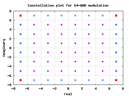
Figure: Constellation plot for 64-QAM modulation (without the scaling factor of )
As can be seen from the above figure, there are three types of constellation points in a general M-QAM constellation:
(a) Constellation points in the corner (red-square)
The number of constellation points in the corner in any M-QAM constellation is always 4, i.e
(b) Constellation points in the inside (magneta-diamond)
The number of constellation points in the inside is,
.
For example with M=64, there are 36 constellation points in the inside.
(c) Constellation points neither at the corner, nor at the center (blue-star) The number of constellation points of this category is,
.
For example with M=64, there are 24 constellation points in the inside.
Additive White Gaussian Noise (AWGN) channel
Let the received symbol is,
, where
is the energy,
is the normalizing factor,
is the transmit symbol and
is the noise.
Assume that the additive noise follows the Gaussian probability distribution function,
with
mean and
variance .
Symbol in the inside (magenta-diamond)
The conditional probability distribution function (PDF) of given that the transmitted symbol is
:
.
As can be seen from the above figure, the symbol in the inside is decoded correctly only if real part of
lies inbetween 0 to 2 and the imaginary part of
lies inbetween 0 to 2. The probability of correct demodulation is,
.
The probability of the real component falling with in 0 to 2 can be found by integrating the probability distribution function of two parts:
(a) Find the probability that the real component lies from to
.
(b) Find the probability that the real component lies from to
.
(c) Given that the total probability is always 1, for finding the probability of the real component lies within to
, subtract the sum of (a) and (b) from 1.
Note: The complementary error function, .
Similarly,
.
From the above equations,
.
The probability of the symbol decoded being in error is,
.
Symbol in the corner (red-square)
The conditional probability distribution function (PDF) of given that the transmitted symbol is
:
.
As can be seen from the above figure, the symbol in the inside is decoded correctly only if real part of
lies from
to
and the imaginary part of
lies from
to
.
.
For finding the probability that the real component lies from to
, one can integrate the probability distribution function of the received symbol.
Similarly,
.
So, probability that the decoded symbol is correct given is transmitted is,
.
Now, the probability of the symbol decoded being in error is,
.
Symbol neither at the corner nor inside (blue-star)
As can be seen from the above figure, the symbol in the inside is decoded correctly only if real part of
lies from
to
and the imaginary part of
lies from 0 to 2.
.
For finding the probability that the real component lies from to
, one can integrate the probability distribution function of the received symbol.
.
As described for the symbol in the inside scenario, the probability of the imaginary component falling with in 0 to 2 can be found by integrating the probability distribution function of two parts:
(a) Find the probability that the imaginary component lies from to
.
(b) Find the probability that the imaginary component lies from to
.
(c) As the total probability is 1, for finding the probability of the imaginary component lies within to
, subtract the sum of (a) and (b) from 1.
So the probability that the symbol is decoded correctly is,
The probability of error is,
.
Total symbol error probability
Given that we have computed the individual symbol error probability for each of the three types of constellation points, to find the joint symbol error rate we compute the average error i.e.
Pluging in the equations,
.
OFDM modulation
Let us use the OFDM system loosely based on IEEE 802.11a specifications.
| Parameter | Value |
| FFT size. nFFT | 64 |
| Number of used subcarriers. nDSC | 52 |
| FFT Sampling frequency | 20MHz |
| Subcarrier spacing | 312.5kHz |
| Used subcarrier index | {-26 to -1, +1 to +26} |
| Cylcic prefix duration, Tcp | 0.8us |
| Data symbol duration, Td | 3.2us |
| Total Symbol duration, Ts | 4us |
Simulation model
Simple Matlab/Octave script for computing the symbol error rate for 16QAM/64QAM and 256QAM modulation scheme in additive white gaussian noise channel over OFDM.
Click here to download : Matlab code for computing symbol error rate for 16QAM/64QAM and 256QAM in AWGN over OFDM
References
[DIG-COMM-BARRY-LEE-MESSERSCHMITT] Digital Communication: Third Edition, by John R. Barry, Edward A. Lee, David G. Messerschmitt
sir plz help me..I need a code for SNR VS BER of different modulation scheme with code rate 1/2 and 3/4.how can i change the code rate.?
@anjali: which coding scheme are you using – convolutional coding?
How can we change the code rate in BER vs SNR simulation?
@anjali: typically, one will have a header field indicating the rate of the transmission
Hi Krishna,
I am trying to simulate SNR of 16-QAM (under Rayleigh fading channel). Any advices on how should I work on as I faced difficulty to generate the matlab.
Regards,
@Jeremiah: That should be relatively easy to code up. The example with BPSK + Rayleigh channel might be of help.
https://dsplog.com/2008/08/10/ber-bpsk-rayleigh-channel/
Thanks Krishna Sankar.
Hi,
could you please tell me if it possible and why when in a OFDM code with this parameters:
k = sqrt(1/10) scaling factor
5 tap long channel
zf and mmse 1 tap equalizer
EbN0dB = [0:36]
EsN0dB = EbN0dB + 10*log10(nDSC/nIFFT) + 10*log10(nIFFT/(nIFFT+CP))
using (16QAM)
The MMSE BER curve is actually higher than the ZF BER curve if I use 16 QAM, but when I use in the same program QPSK I get the normal result (MMSE better than ZF)???
I used all the scaling factor that i found in your posts on ofdm and 16QAM and I added to the received signal the noise as 10^(-EsN0dB(ii)/20)*n.
When I perform MMSE I use
C= (1./(conj(hF).*hF+10^(-EsN0dB(ii)/20))).*conj(hF);
y_mse = yF.*C;
The modulation and demodulation is done by
Mod = modem.qammod(‘M’, 16, ‘PhaseOffset’,0,’SymbolOrder’,’gray’,’InputType’,’bit’);
Dem = modem.qamdemod(Mod);
using modulate and demodulate command.
I tried to use one tap channel but I get the same result so I think is not becuse I should use some taps at the equalizer.What I mean is that with 16QAM in Ray channel can one tap MMSE equalizer be worse than one tap ZF or I miss some scaling factor in the equalization or in other parts????
Thanks,
R.
To give you a better idea of what I get I attached the link below of the curves that i get when I use QPSK and 16QAM in OFDM with the same parameters (CP,nBits etc..). In QPSK case I get perfectly identical BER for ZF and MMSE.
http://www.4shared.com/photo/QgFiaXQX/untitled.html
Could it be because of MMSE have only one tap and if I d use 3 or 5 taps MMSE curve will be lower than ZF one??
Regards,
R.
@riccardo: Why is MMSE so poor for 16QAM case? Is the noise variance term in order?
@riccardo; Should we use scaling of 1/10 for the noise variance?
C= (1./(conj(hF).*hF+10^(-EsN0dB(ii)/10))).*conj(hF);
I did it and it looks better but still ZF outperforms MMSE. Here is the ber.
http://www.4shared.com/photo/gA-Hzpzv/untitledu.html
However, I know I’m missing something stupid but I can’t figured it out…Would you mind having a further look to the whole program which work for QPSK but not for 16QAM? I send send an email and we can try to sort it out.
I’m doing a BER comparison between OFDMA and SCFDMA in SISO SIMO and MIMO scenarios, once I got them correctly if you like we can write a post in this blog so it would be helpfull for everyone 😉
Let me know.
Regards,
R.
I sent a email to you with the code.
Thanks.
@riccardo: Given the time constraints, debugging through the code is slightly difficult. Good luck
Hello Sir ,
Can you please advise me , how can i modify this code to use QPSK modulation along with the QAM modulations. I am in desperate need for my project to observe different types of modulation schemes on OFDM system.
Thanks & best Regards
@Mostafa: Try putting M=4 in the simulations for QPSK.
first of all thanks a lot for your efforts. I am new in matlab and I want to ask you about some instructions in your matlab code.
1- why have u used this instruction even u can use idft directly
xt = (nFFT/sqrt(nDSC))*ifft(fftshift(xF.’)).’;
2- what do u mean by this instruction
xF = [zeros(nOFDMsym,6) ipMod_norm(:,[1:nConstperOFDMsym/2]) zeros(nOFDMsym,1) ipMod_norm(:,[nConstperOFDMsym/2+1:nConstperOFDMsym]) zeros(nOFDMsym,5)] ;
3- I haven’t understand the addition of cyclic prefix
finnaly can u explain what represent all of this instructions in practice
thanks in advance
@houda: My replies:
1/ the term (nFFT/sqrt(nDSC)) is for scaling the output power.
the term fftshift() is to provide the frequency domain information in the way ifft() likes.
please check the post on negative frequency
https://dsplog.com/2008/08/08/negative-frequency/
https://dsplog.com/2008/02/03/understanding-an-ofdm-transmission/
2/ This is forming the xF, a matrix of dimension [ number of ofdm symbols x number of subcarriers]
In this example, i recon the number of subcarriers is 64. And the index
[-32:-27] : 6 subcarriers are 0
[-26:-1] : 26 data subcarriers
0 : no information on dc subcarrier
[1:26] : 26 data subcarriers
[27:31] : 5 subcarriers are 0
3/ Cyclic prefix is added to provide a buffer zone for inter symbol interference from the previous symbol caused due to the multipath channel
https://dsplog.com/2008/02/17/cylcic-prefix-in-orthogonal-frequency-division-multiplexing/
thanks a lot Krishna Sankar.
I have simple queation!!
at OFDM, increasing FFT size , how about BER curve?? and why??
please, answer my queation!
@doojin: For the same sampling frequency, increasing the fft size means that the subcarrier spacing is narrower resulting in a lower noise power. However we need to lower transmit power of each subcarrier by the same amount to keep the transmit power a constant. Hence, I reckon there is no Eb/N0 vs BER impact by increasing the number of subcarriers.
hello.thank you very much for matlab code 16-QAM.
I want this matlab code for 64-QAM but by change 16 to 64 I cant simulation.help me
Best Regards.
Hello Krishna,
i am sachin. i need some help from you.
i need matlab code for ostbc over nakagami-m channel or BER for the nakagami-m channel.waiting for your feedback and your help.
@sachin: I do not have topics on the articles you described above. But can point you to https://dsplog.com/tag/ofdm
Hello Krishna,
i am imran. i need some help from you. i need a theoretical formula of Bit Error Rate or Symbol error rate for 16-APSK (amplitude phase shift keying). i got the simulation result . but i dont know the exact theoretical formula or equation regarding of this problem.
I saw some of your updated formula for 16-QAM or 16- PSK. i want the like this formula where i can compare my theoretical and simulation constellation plot.
waiting for your feedback and your help.
@imran: sorry, i have not discussed 16APSK schemes in the posts
Thanks Krishna for your feedback.
i would like to request you, please give me some suggestion where i can get this information. Honestly i need desperately this 16-apsk theoretical formula for BER or SER.
your welcome.
you should write about Es : Es_max, Es_min, Es_avrage.
Do you know the formula for OFDM based on 64QAM modulation?
@ofir: Hmmm… the underlying equation for 64QAM will remain the same even in OFDM case. The presence of cyclic prefix, guard subcarriers will mean that the noise scaling needs to be adjusted appropriately.
https://dsplog.com/2012/01/01/symbol-error-rate-16qam-64qam-256qam/
No it will not. In OFDM there are 48 subcarriers of 64qam tansmitted. It changes the SER. The more subcarries you add the bigger the bandwidth becomes, the longer Tsymbol is.
@ofir: Well, the slope of the symbol error rate does not change. Yes, it does get shifted in the x-axis based on the cyclic prefix and the number of subcarriers. I have discussed about a simple BPSK case at https://dsplog.com/2008/06/10/ofdm-bpsk-bit-error/
Es/N0 dB = Eb/N0 dB + 10*log10(ndsc/nfft) + 10*log10(td/(td+tcp))
any one can give the matlab code for ostbc over nakagami-m channel or BER for the nakagami-m channel
you have a mistake on “K”.
it does not equal to SQRT(1/(2/3*M-1)).
it’s equal to SQRT(1/(2/3*(M-1)))
@ofir: Hmm… it is SQRT(1/(2/3*(M-1))). Where do you see the error?
look at your k.
k=SQRT(1/(2/3*M-1).
I calculated it and it’s equal to: k=SQRT(1/(2/3*(M-1))).
@ofir: M-1 is in the numerator
No it is not.
under “Additive White Gaussian Noise (AWGN) channel ”
look at “k”
__________
/ 1
k= /___________
/ _2_ * M-1
\/ 3
when it should be:
__________
/ 1
k= /___________
/ _2_ * (M-1)
\/ 3
@ofir: At last, I understood your concern – and I added bracket’s around (M-1). Thanks for pointing that out. It was a typo from my side.
hello
please help me simulation the difference between DVB-T and DVB-T2, i am not good at MATLAB, i have searched a document but i can’t do it because i don’t know how to write progam with matlab.
thankyou very much!
this is link: http://www.dtg.org.uk/dtg/t2docs/Validation_Simulation_Interoperability_Andrew_Murphy_BBC.pdf
@thang: sorry, wont be able to help you with the coding part.
for ofdm related posts, plz check out https://dsplog.com/category/ofdm/
I can not run for this project, there is an error in –>
“??? Error using ==> semilogy
Conversion to double from cell is not possible.
Error in ==> compute_symbol_error_rate_qam_ofdm_awgn at 27
semilogy(EsN0dB,theorySer(jj,:),color_vec1(jj));”
@reza: try replacing color_vec1(jj) with color_vec1{jj}
thanks sir. it works!
good job