Question 34 on signals from GATE (Graduate Aptitude Test in Engineering) 2012 Electronics and Communication Engineering paper.
Year: 2012
GATE-2012 ECE Q12 (math)
Question 12 on math from GATE (Graduate Aptitude Test in Engineering) 2012 Electronics and Communication Engineering paper.
Q12. With initial condition =0.5}) the solution of the differential equation,
the solution of the differential equation,
 is
is
(A) 
(B) 
(C) 
(D) 
![]()
Solution
From the product rule used to find the derivative of product of two or more functions,
Applying this to the above equation, we can be seen that,
Plugging this in and integrating both sides,
.
Using the initial condition , we can solve for the unknown
, i.e.
.
So the solution to the differential equation is,
Based on the above, the right choice is (D) .
References
[1] GATE Examination Question Papers [Previous Years] from Indian Institute of Technology, Madras http://gate.iitm.ac.in/gateqps/2012/ec.pdf
[2] Wiki entry on Product rule
GATE-2012 ECE Q11 (signals)
Question 11 on signals from GATE (Graduate Aptitude Test in Engineering) 2012 Electronics and Communication Engineering paper.
Q11. The unilateral Laplace transform of}) is
is  . The unilateral Laplace transform of
}) is
is
(A) ^2}})
(B) ^2})
(C) ^2}})
(D) ^2})
GATE-2012 ECE Q2 (communication)
Question 52 on communication from GATE (Graduate Aptitude Test in Engineering) 2012 Electronics and Communication Engineering paper.
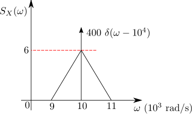
Q2. The power spectral density of a real process}) for positive frequencies is shown below. The values of
for positive frequencies is shown below. The values of \]}) and
and \]\|}) , respectively are
, respectively are
(A) 
(B) 
(C) })
(D) })
![]()
Solution
For a wide sense stationary function, the auto-correlation with delay is defined as,
From the Weiner-Kinchin theorem, the auto-correlation function and power spectral density
are Fourier Transform pairs, i.e.
Expressing in terms of , where
.
When the delay , the above equations simplifies to
.
Applying this to the problem at hand,
.
Further, since the power spectral density does not have any dc component, the mean of the signal
Based on the above, the right choice is (B)
References
[1] GATE Examination Question Papers [Previous Years] from Indian Institute of Technology, Madras http://gate.iitm.ac.in/gateqps/2012/ec.pdf
[3] Wide sense stationary function
[4] Auto-correlation
GATE-2012 ECE Q52 (electromagnetics)
Question 52 on electromagnetics from GATE (Graduate Aptitude Test in Engineering) 2012 Electronics and Communication Engineering paper.
An infinitely long uniform solid wire of radius  carries a uniform dc current of density
  .
.
Q52. The magnetic field at a distance  from the center of the wire is proportional to
(A) for  and
and  for
for 
(B)  for and
  for
for
(C) for and for
(D) for and for
![]()
Solution
To answer this question on magnetic field, we need to determine the magnetic field inside and outside the cable using Ampere’s Law.
Ampere’s Law :
The total current inside a closed curve
is the line integral of the magnetic field
(in Tesla)
,
where
is the magnetic field (in Tesla)
is the vector representing the infinitesimal line on the closed loop
,
is the net current enclosed by the closed loop and
is the permeability of vacuum.
Let us use this result to find the magnetic field in a uniform solid wire of radius .
Magnetic field in the region :

Figure : Solid wire showing the imaginary Amperian loop inside the wire (circle with radius )
Given that the current density is , the current through the area in the circle with radius
is
Applying Ampere’s law,
,
where
is the permeability (
is the permeability of vacuum.
is the permeability of the material).
Given that the magnetic field is is parallel to the line
and is uniform across the closed loop, it can be moved out of the integral, i.e
.
The term is the circumference of the circle with radius
i.e.
.
Substituting, the magnetic field in the region is,
.
Magnetic field in the region :

Figure : Solid wire showing the imaginary Amperian loop outside the wire (circle with radius )
Given that the current density is , the current through the area in the circle with radius
is determined only by the current flowing through the cable with in the radius
, i.e.
Applying Ampere’s law,
,
Taking outside the intergral and substituting for the term
,
The magnetic field in the region is,
.
Summarizing,
Based on the above, the right choice is (C) i.e. The magnetic field at a distance from the center of the wire is proportional to
for
and
for
References
[1] GATE Examination Question Papers [Previous Years] from Indian Institute of Technology, Madras http://gate.iitm.ac.in/gateqps/2012/ec.pdf
[2] Fields and Waves in Communication Electronics, Simon Ramo, John R. Whinnery, Theodore Van Duzer (buy from Amazon.com, buy from Flipkart.com).
[3] The youtube videos uploaded by user lasseviren1 aided me in understanding the integrals in electric field and magnetic field.
[4] Ampere’s Law
[5] Permeability
GATE-2012 ECE Q16 (electromagnetics)
Question 16 on electromagnetics from GATE (Graduate Aptitude Test in Engineering) 2012 Electronics and Communication Engineering paper.
Q16. A coaxial cable with an inner diameter of 1mm and outer diameter of 2.4mm is filled with a dielectric of relative permittivity 10.89. Given  , the characteristic impedance of the cable is
(A) 
(B) 
(C) 
(D) 
![]()
Solution
To answer this question, am referring to the discussion on capacitance per unit length (Section 1.9) , inductance per unit length (Section 2.4) and characteristic impedance (Section 5.2) of a coaxial cable from Fields and Waves in Communication Electronics, Simon Ramo, John R. Whinnery, Theodore Van Duzer (buy from Amazon.com, buy from Flipkart.com).
Finding the capacitance per unit length:
Using Gauss law :
For a closed Gaussian surface , the electrical flux is given by :
, where
is the electrical flux,
is the electric field,
is the vector representing the infinitesimal area on the surface
,
is the net charge enclosed by the surface and
is the permittivity of vacuum.
Let us use this result to find the electrical field in a coaxial cable formed by two conducting cylinders of radii and
respectively with a dielectric
between them (shown in the figure below).

Figure : Coaxial cable showing the imaginary Gaussian surface (cylinder with radius and length
)
For finding the electric field in region
, assume a cylindrical Gaussian surface of radius
and length
(as shown by the dashed line).
Applying Gauss law,
,
where
is the charge per unit length,
total charge enclosed is the charge per unit length multiplied by the length i.e. and
is the permittivity (
is the permittivity of vacuum,
is the permittivity of the material).
Given that the electrical field is is parallel to the surface
and is uniform across the Gaussian surface, it can be moved out of the integral, i.e
.
The term is the surface area of the cylinder with radius
of length
and is,
.
Substituting, the electric field in the region is,
.
With the above electric field, the potential difference between the coaxial cylinders is computed as,
.
The capacitance between two electrodes is defined as the charge on each electrode per volt of potential difference
between then,
.
Assuming that the field is only radial and the total charge per unit length is , the capacitance per unit length is
.
Finding the inductance per unit length:
Using Ampere’s Law :
The total current inside a closed curve
is the line integral of the magnetic field
(in Tesla)
,
where
is the magnetic field (in Tesla)
is the vector representing the infinitesimal line on the closed loop
,
is the net current enclosed by the closed loop and
is the permeability of vacuum.
Let us use this result to find the magnetic field in a coaxial cable formed by two conducting cylinders of radii and
respectively with a dielectric having permeability of
between them (shown in the figure below).

Figure : Coaxial cable showing the imaginary Amperian loop (circle with radius )
Applying Ampere’s law,
,
where
is the permeability (
is the permeability of vacuum.
is the permeability of the material).
Given that the magnetic field is is parallel to the line
and is uniform across the closed loop, it can be moved out of the integral, i.e
.
The term is the circumference of the circle with radius
and is,
.
Substituting, the magnetic field in the region is,
.
The inductance is defined as ratio of magnetic field over a surface and the the current.
.
For a unit length, the integral of magnetic field in the region is,
.
Substituting, the inductance per unit length is,
.
Note :
YouTube videos uploaded by user lasseviren1 aided me in understanding the integrals in electric field and magnetic field. Do checkout the play-lists : Gauss’s Law , Sources of Magnetic Fields
The characteristic impedance :
From wiki entry on characteristic impedance, the general expression for the characteristic impedance of a transmission line is
,
where,
is the resistance per unit length,
is the inductance per unit length,
is the capacitance per unit length,
is the conductance per unit length and
is the angular frequency.
Assuming a loss less transmission line, i.e. , the equation reduces to,
.
Substituting the expressions for inductance per unit length and capacitance per unit length for a coaxial cable,
.
Substituting the numbers from the problem at hand,
,
the characteristic impedance is,
.
The calculated choice is not listed in the options. However if we ignore the term, the calculated number comes to around
. That does not help, does it? 🙂
References
[1] GATE Examination Question Papers [Previous Years] from Indian Institute of Technology, Madras http://gate.iitm.ac.in/gateqps/2012/ec.pdf
[2] Fields and Waves in Communication Electronics, Simon Ramo, John R. Whinnery, Theodore Van Duzer (buy from Amazon.com, buy from Flipkart.com).
[3] The youtube videos uploaded by user lasseviren1 aided me in understanding the integrals in electric field and magnetic field. Do checkout the play-lists : Gauss’s Law
[5] Ampere’s Law
[6] Gauss law
[7] Permeability
[8] Permittivity
[9] Electrical Flux
GATE-2012 ECE Q39 (communication)
Question 39 on communication from GATE (Graduate Aptitude Test in Engineering) 2012 Electronics and Communication Engineering paper.
Q39. The signal }) as shown is applied both to a phase modulator (with
as shown is applied both to a phase modulator (with  as the phase constant) and a frequency modulator (with
  as the frequency constant) having the same carrier frequency.

The ratio  }) for the same maximum phase deviation is,
for the same maximum phase deviation is,
(A) 
(B) 
(C) 
(D) 
![]()
Solution
To answer this question, let us understand basics of Frequency modulation and Phase modulation. Am referring to the discussion in Section 10 of Electronic Communication, 4th Edition, Dennis Roddy, John Coolen (buy from Amazon.com, buy from Flipkart.com).
Frequency Modulation
In frequency modulation, the modulation signal will cause a change in the instantaneous carrier frequency and is related as
where
is the frequency deviation constant expressed in hertz/volt (Hz/V) and
is the carrier frequency in Hz.
The angular velocity radians per second.
Since the rate of change of phase is the angular velocity,
and so, the instantaneous phase is
.
The frequency modulated carrier signal is
Phase modulation
In phase modulation, the modulation signal will cause a change in phase and the instantaneous phase is
where
is the phase deviation constant expressed in radians/volt and
is the carrier frequency in radians per second.
The phase modulated carrier signal is
.
Now, applying the above equations to solve the problem :
In frequency modulation case, the maximum phase deviation happens when the term hits the maximum.
In phase modulation case, the maximum phase deviation happens when the term hits the maximum.
.
The ratio is,
and so,
Based on the above, the right choice is (B)
References
[1] GATE Examination Question Papers [Previous Years] from Indian Institute of Technology, Madras http://gate.iitm.ac.in/gateqps/2012/ec.pdf
[2] Electronic Communication, 4th Edition, Dennis Roddy, John Coolen (buy from Amazon.com, buy from Flipkart.com).
GATE-2012 ECE Q47 (math)
Question 47 on math from GATE (Graduate Aptitude Test in Engineering) 2012 Electronics and Communication Engineering paper.
Q47. Given that
 and
and  , the value of
  is
is
(A) 
(B) 
(C) 
(D) 
![]()
Solution
To answer this question, we need to refer to Cayley Hamilton Theorem. This is discussed briefly in Pages 310-311 of Introduction to Linear Algebra, Glibert Strang (buy from Amazon.com, buy from Flipkart.com)
From the wiki entry on Cayley Hamilton theorem,
If is a given
matrix, and
is the
identity matrix, the characteristic polynomial of
is defined as,
.
The Cayley Hamilton theorem states that substituting matrix for
in this polynomial results in a zero matrix, i.e.
This theorem allows for to be expressed as linear combination of the lower matrix powers of
.
For a general 2×2 matrix the theorem is relatively easy to prove.
Let
The characteristic polynomial is
Substituting by matrix in the polynomial,
.
Now, applying Cayley Hamilton theorem to the problem at hand,
.
The characteristic polynomial is,
.
Substituting by matrix in the polynomial,
.
Alternatively, .
Finding in terms of
by substituting for
,
Matlab example
>> A = [-5 -3 ; 2 0];
>> A^3
ans =

  -65  -57
   38   30

>> 19*A + 30*eye(2)
ans =

  -65  -57
   38   30
Based on the above, the right choice is (B) .
References
[1] GATE Examination Question Papers [Previous Years] from Indian Institute of Technology, Madras http://gate.iitm.ac.in/gateqps/2012/ec.pdf
[2] Introduction to Linear Algebra, Glibert Strang (buy from Amazon.com, buy from Flipkart.com)
[3] wiki entry on Cayley Hamilton theorem
Update : Correction to solution of GATE-2012 ECE Q38
Thanks to Mr. Raghava G D’s comments on the post discussing Question 38 on Communication from GATE (Graduate Aptitude Test in Engineering) 2012 Electronics and Communication Engineering paper, realized that I had made an error in the solution. Have the updated the post with the right answer and additional explanations.
Continue reading “Update : Correction to solution of GATE-2012 ECE Q38”
GATE-2012 ECE Q38 (communication)
Question 38 on Communication from GATE (Graduate Aptitude Test in Engineering) 2012 Electronics and Communication Engineering paper.
Q38. A binary symmetric channel (BSC) has a transition probability of 1/8. If the binary transmit symbol X is such that P(X=0)=9/10, then the probability of error for an optimum receiver will be
(A) 7/80
(B) 63/80
(C) 9/10
(D) 1/10
![]()
Solution
The solution to the problem seem deceptively reasonably simple. Quoting from the Wiki entry on Binary Symmetric Channel
A binary symmetric channel (or BSC) is a common communications channel model used in coding theory and information theory. In this model, a transmitter wishes to send a bit (a zero or a one), and the receiver receives a bit. It is assumed that the bit is usually transmitted correctly, but that it will be “flipped” with a small probability (the “crossover probability”). This channel is used frequently in information theory because it is one of the simplest channels to analyze.”
In our example, the transition probability i.e probability of transition (i.e. 1 becoming 0 or 0 becoming 1) for each alphabet is given as 1/8. probability of correct transmission, for each alphabet is given as 1/8 (the probability of incorrect transition is 7/8).
The transition probability diagram with the above data can be drawn as,
![]()
Figure : Transition probability diagram for a binary symmetric channel
The probability of the source alphabets are,
.
The transition probability when is :
.
Similarly the transition probability when is :
.
The received alphabet not equal to the transmitted alphabet is,
.
Hold on, we are not done yet.
Update (9th Nov 2012):
The above gives the probability that the received symbol is not equal to the transmitted symbol, and not the probability of error for an optimum detector. Thanks to Mr. Raghava GD who rightly pointed out in the comment section that – “the calculation that you did just gives the probability of receiving the bit erroneously and it doesn’t tell anything about the probability of error for an optimum decoder.”
After digesting his comments, and referring from Section of 1.2 of Chapter 1 of Prof. John M. Cioffi’s book ,
Consider the channel model which produces a discrete vector output for a discrete vector input. The detector chooses a message from all possible messages
transmit vectors. The channel input vector
results in a corresponding channel output vector
. The decision device translates the received vector
to an estimate of the transmitted vector
and a decoder converts
to the estimate of the message vector
.

Figure : Vector channel model (Reference : Figure 1.13 in Chapter 1 of Prof. John M. Cioffi’s book)
The probability of error is defined as,
.
Correspondingly, the probability of being correct is,
.
The optimum detector chooses to minimize the probability of error
or equivalently maximize
.
The probability of making the correct decision , given the received vector
is
.
The above quantity known as the posteriori probability, and an optimum decision device will try to maximize the above quantity. The Maximum a Posteriori Detector (MAP), is defined as the detector that chooses the index to maximize the a posterior probability
given the received vector
.
Using Bayes therorem, the posterior probability can be written in terms of prior probability and the channel transition probability
,
.
Note :
The term is a constant and can be ignored when trying to maximize the posterior probability
.
The MAP detection rule is,
.
Note :
This is discussed briefly in Chapter 5.1.3 The Optimum Detector in Digital Communications, Fourth edition John G. Proakis (buy from Amazon.com, buy from Flipkart.com)
Applying the MAP detection rule to the problem at hand :
We have two candidates 0 and 1 for the source message i.e
a) ,
b) modulator is a pass through i.e and
c) received symbol can be 0 or 1.
The goal is to make decision rule on the observed received symbol .
Applying MAP detection rule,
.
.
In both the cases i.e when received symbol , the optimum MAP detection rule suggest that the estimated message symbol is
.
Intuitively, this makes sense : given that , a receiver will be better of assuming that the transmitted symbol is always 0. With this, the probability of making an error in the decision is
.
Matlab example
clear all; close all;
% number of observations
N = 10^5;
% generating x with p(x=0) = 9/10, p(x=1) = 1/10
x = (rand(1,N) > 9/10);
% generating c with p(c=0) = 1/8, p(c=1) = 7/8
c = (rand(1,N) < 7/8);
% binary symmetric channel
y = mod(x+c,2);
xhat = 0;
% counting errors
nErr    = size(find(xhat-x),2);
errProb = nErr/N
Based on the above, the right choice is (D) 1/10.
References
[1] GATE Examination Question Papers [Previous Years] from Indian Institute of Technology, Madras http://gate.iitm.ac.in/gateqps/2012/ec.pdf
[2] Wiki entry on Binary Symmetric Channel http://en.wikipedia.org/wiki/Binary_symmetric_channel
[3] Chapter 1 of Prof. John M. Cioffi’s book
[4] Wiki entry on posteriori probability
[5] Wiki entry on Bayes therorem
[6] Digital Communications, Fourth edition John G. Proakis (buy from Amazon.com, buy from Flipkart.com)
GATE-2012 ECE Q3 (communication)
Question 3 on Communication from GATE (Graduate Aptitude Test in Engineering) 2012 Electronics and Communication Engineering paper.
Q3. In a baseband communications link, frequencies upto 3500Hz are used for signalling. Using a raised cosine pulse with 75% excess bandwidth and for no inter-symbol interference, the maximum possible signaling rate in symbols per second is,
(A) 1750
(B) 2625
(C) 4000
(D) 5250
![]()
Solution
To answer this question, am using contents from Section 5.1 of Digital Communication, third edition, John R. Barry, Edward A. Lee, David G. Messerschmitt (buy from Amazon.com, buy from Flipkart.com).
Let us first try to understand the minimum bandwidth required to transmit the signal at symbol rate
with no inter symbol interference (ISI).
The transmitted signal is,
,
where
is the
transmitted data symbols,
is the symbol rate and
is the pulse shape.
The sampled signal is,
.
Decomposing the above equation into two parts,
.
The first term is the desired signal and the second term contributes to inter symbol interference.
To ensure that there is no intersymbol interference, the sampled pulse shape should be
.
Taking Fourier transform, this translates to the following criterion
.
Note : For convenience, take
.
Note :
The proof for this is discussed in bit more detail in Section 9.2 of Digital Communications, 4th edition John G. Proakis (buy from Amazon.com, buy from Flipkart.com)
Let us assume that pulse shape has a bandwidth
. There are three cases to check
i) When :
In this case, the plot of will have non-overlapping replicas of the spectrum
separated by
and there is no choice to meet the
criterion.
ii) When :
There exists one candidate meeting the criterion,
.
The corresponding pulse shape is
.
Alternately, this can be stated as – for a given single sided bandwidth , the maximum symbol rate which can be achieved for ISI free transmission is
. To meet this, the pulse shape
has to be a sinc function. Typically usage of the sinc function is not preferred as its tails decay very slowly and a small timing error in the demodulator will result in an infinite series of inter symbol interference components.
iii) When
In this case consists of overlapping spectrum of
separated by
and there exists multiple choices meeting the
criterion.
A commonly used pulse shaping filter satisfying the criterion while having a faster decay is the raised cosine filters having the following equation,
.
The frequency response is,
.
With a raised cosine pulse shape, the bandwidth is larger than the minimum required pulse shape and is related as,
.
Then term is called the excess bandwidth factor. For example,
translates to 75% excess bandwidth
translates to 100% excess bandwidth
, the raised cosine pulse shape reduces to sinc pulse shape.
In our question,
and
and the goal is to find the maximum possible symbol rate
.
Substituting for ,
and solving for
,
.
Matlab example
% script for plotting the time and frequency response of raised cosine pulse shape
% filter with
% a) alpha = 0 (sinc pulse)
% b) alpha = 3/4
%
clear all; close all;

fs = 10;
% defining the sinc filter
sincNum = sin(pi*[-fs:1/fs:fs]); % numerator of the sinc function
sincDen = (pi*[-fs:1/fs:fs]); % denominator of the sinc function
sincDenZero = find(abs(sincDen) < 10^-10);
sincOp = sincNum./sincDen;
sincOp(sincDenZero) = 1; % sin(pix/(pix) =1 for x =0

alpha = 0;
cosNum = cos(alpha*pi*[-fs:1/fs:fs]);
cosDen = (1-(2*alpha*[-fs:1/fs:fs]).^2);
cosDenZero = find(abs(cosDen);
cosOp(cosDenZero) = pi/4;
gt_alpha0 = sincOp.*cosOp;
GF_alpha0 = (1/fs)*fft(gt_alpha0,1024);

alpha = 0.75;
cosNum = cos(alpha*pi*[-fs:1/fs:fs]);
cosDen = (1-(2*alpha*[-fs:1/fs:fs]).^2);
cosDenZero = find(abs(cosDen);
cosOp(cosDenZero) = pi/4;
gt_alpha0 = sincOp.*cosOp;
GF_alpha0 = (1/fs)*fft(gt_alpha0,1024);

alpha = 0.75;
cosNum = cos(alpha*pi*[-fs:1/fs:fs]);
cosDen = (1-(2*alpha*[-fs:1/fs:fs]).^2);
cosDenZero = find(abs(cosDen)
cosOp(cosDenZero) = pi/4;
gt_alpha_p75 = sincOp.*cosOp;
GF_alpha_p75 = (1/fs)*fft(gt_alpha_p75,1024);

Figure : Time domain plot

Figure : Frequency domain plot
Based on the above, the right choice is (C) 4000 symbols per second.
References
[1] GATE Examination Question Papers [Previous Years] from Indian Institute of Technology, Madras http://gate.iitm.ac.in/gateqps/2012/ec.pdf
[2] Digital Communication, Third edition, John R. Barry, Edward A. Lee, David G. Messerschmitt (buy from Amazon.com, buy from Flipkart.com)
[3] Digital Communications, Fourth edition John G. Proakis (buy from Amazon.com, buy from Flipkart.com)
GATE-2012 ECE Q26 (electronic devices)
Question 26 on Electronic Devices from GATE (Graduate Aptitude Test in Engineering) 2012 Electronics and Communication Engineering paper.
Q26. The source of a silicon ( ), n-channel MOS transistor has an area of
  and a depth of
  . If the dopant density in the source is
  , the number of holes in the source region with above volume is approximately
(A) 
(B) 
(C) 
(D) 
![]()
Solution
To answer this question, had to dig up the copy of Solid State Electronic Devices, Ben G Streetman, Sanjay Kumar Banarjee (buy from Amazon.com, buy from Flipkart.com) and am referring to the content from Section 3.3 Carrier Concentrations.
Electrons in solids obey Fermi-Dirac statistics. The function Fermi-Dirac distribution function, gives the probability that an available energy state at
will be occupied by an electron at absolute temperature
,
.
The quantity is the Fermi level and
is the Boltzmann’s constant.
The concentration of electrons in the conduction band is,
, where
is the density of states
in the energy range
.
The integral is equivalently stated as,
, where
is the effective density of states at conduction band edge
.
The Fermi function at is approximately,
.
So in this condition the concentration of electrons in the conduction band is,
.
Similarly, the concentration of holes in the valence band is,
, where
is the effective density of states at valence band edge
.
The term,
.
So in this condition the concentration of holes in the valence band is,
.
The product of and
at equilibrium is a constant for a particular material and temperature even if doping is varied.
, where
is the gap between the conduction band and valence band.
Similarly, for an intrinsic material, the product of and
is,
For an intrinsic material, the electron and hole concentration are equal i.e. .
The constant product of electron and hole concentration can be written as
With the above understanding, let us try to find the solution to the problem. In our question,
and
.
The hole concentration is,
.
The volume of the source region is
.
The number of holes is,
Based on the above, the right choice is (D) 0.
References
[1] GATE Examination Question Papers [Previous Years] from Indian Institute of Technology, Madras http://gate.iitm.ac.in/gateqps/2012/ec.pdf
[2] Solid State Electronic Devices, Ben G Streetman, Sanjay Kumar Banarjee (buy from Amazon.com, buy from Flipkart.com)
[3] Valence band http://en.wikipedia.org/wiki/Valence_band
[4] Conduction band http://en.wikipedia.org/wiki/Conduction_band
GATE-2012 ECE Q36 (math)
Question 36 on math from GATE (Graduate Aptitude Test in Engineering) 2012 Electronics and Communication Engineering paper.
Q36. A fair coin is tossed till a head appears for the first time. The probability that the number of required tosses is odd, is
(A) 1/3
(B) 1/2
(C) 2/3
(D) 3/4
![]()
Solution
Let us start by finding the sample space. The possible sample space with odd number of tosses till a head appears for the first time is,
Given that the coin is fair,
.
The total probability is,
Using Taylor series,
.
Substituting,
Matlab/Octave example
Felt it would be nice to get similar results using a simple simulation model
% Script to find the probability that odd number of tosses
% are required to get a head for the first time

clear all; close all;
N = 5*10^5;

% HEAD = 0, TAIL = 1;
% definfing the pattern corresponding to odd tosses
% till the first head - limiting to max of 21 tosses
% converted to integer (for easy comparison)
pattern_v = [ ...
   sum(2.^0         .*  [0 ]);                      ... % H
   sum(2.^(2:-1:0)  .*  [1 1 0 ]);                  ... % TTH
   sum(2.^(4:-1:0)  .*  [1 1 1 1 0 ]);              ... % TTTTH
   sum(2.^(6:-1:0)  .*  [1 1 1 1 1 1 0 ]);          ... % TTTTTTH
   sum(2.^(8:-1:0)  .*  [1 1 1 1 1 1 1 1 0 ]);      ... % TTTTTTTTH ...
   sum(2.^(10:-1:0) .*  [1 1 1 1 1 1 1 1 1 1 0 ]);  ...
   sum(2.^(12:-1:0) .*  [1 1 1 1 1 1 1 1 1 1 1 1 0 ]); ...
   sum(2.^(14:-1:0) .*  [1 1 1 1 1 1 1 1 1 1 1 1 1 1 0 ]); ...
   sum(2.^(16:-1:0) .*  [1 1 1 1 1 1 1 1 1 1 1 1 1 1 1 1 0 ]); ...
   sum(2.^(18:-1:0) .*  [1 1 1 1 1 1 1 1 1 1 1 1 1 1 1 1 1 1 0 ]); ...
   sum(2.^(20:-1:0) .*  [1 1 1 1 1 1 1 1 1 1 1 1 1 1 1 1 1 1 1 1 0 ]); ...
  ];

% finding the probability for each event in the  sample space
event_v = [1:2:21];
for ii=1:length(event_v)
   kk           = event_v(ii);
   x            = rand(N,kk)>0.5;
   xVal         = sum((ones(N,1)*[2.^([kk-1:-1:0])]).*x,2);
   matchCnt(ii) = size(find(xVal==pattern_v(ii)),1);
end
totalProb = sum(matchCnt./N)

Figure : Probability of odd number of tosses till first head
Based on the above, the right choice is (C) 2/3.
References
[1] GATE Examination Question Papers [Previous Years] from Indian Institute of Technology, Madras http://gate.iitm.ac.in/gateqps/2012/ec.pdf
[2] Wiki entry on Taylor series http://en.wikipedia.org/wiki/Taylor_series
GATE-2012 ECE Q46 (math)
Question 46 on math from GATE (Graduate Aptitude Test in Engineering) 2012 Electronics and Communication Engineering paper.
Q46. The maximum value of  = x^3 - 9x^2 + 24x + 5}) in the interval [1, 6] is
in the interval [1, 6] is
(A) 21
(B) 25
(C) 41
(D) 46
![]()
Solution
Let us start by finding the critical points of the function .
The first derivative is,
.
Solving by setting .
.
Taking second derivative, .
At and this corresponds to a local minimum.
At and this corresponds to a local maximum.
The value of the function at these critical points are,
.
Hold on, we are not done yet… 🙂
From the wiki entry on Extereme Value Theorem,
In calculus, the extreme value theorem states that if a real-valued function f is continuous in the closed and bounded interval [a,b], then f must attain its maximum and minimum value, each at least once. That is, there exist numbers c and d in [a,b] such that:
.
Further, from wiki entry on finding maxima and minima,
If a function is continuous on a closed interval, then by the extreme value theorem global maxima and minima exist. Furthermore, a global maximum (or minimum) either must be a local maximum (or minimum) in the interior of the domain, or must lie on the boundary of the domain. So a method of finding a global maximum (or minimum) is to look at all the local maxima (or minima) in the interior, and also look at the maxima (or minima) of the points on the boundary; and take the biggest (or smallest) one.
For our example, the function is real valued and is continuous in the closed and bounded interval [1,6].
Finding out the value of the function at the boundaries,
.
So the global maximum of the function in the interval [1, 6] is
and it occurs at the boundary i.e. x = 6.
Matlab example
clear all; close all;
x = [1:.1:6];
fx = x.^3 - 9*x.^2 + 24*x + 5;
plot(x,fx);
xlabel('x'); ylabel('fx');
grid on; axis([1 6 20 45]);
title('fx  =  x^3 - 9x^2 + 24x + 5');

Figure : Plot of the function in the interval [1,6]
From the figure, it is relatively easy to observe that the maximum is hit at x=6 (and not at the local maximum point of x=2).
Based on the above, the right choice is (C) 41.
References
[1] GATE Examination Question Papers [Previous Years] from Indian Institute of Technology, Madras http://gate.iitm.ac.in/gateqps/2012/ec.pdf
[2] Wiki entry on Extreme Value Theorem
http://en.wikipedia.org/wiki/Extreme_value_theorem
[3] Wiki entry on Maxima and Minima