In the past, we had discussed BER for BPSK in flat fading Rayleigh channel and BER for BPSK in a frequency selective channel using Zero Forcing Equalization. In this post, lets discuss a frequency selective channel with the use of Minimum Mean Square Error (MMSE) equalization to compensate for the inter symbol interference (ISI). For simplifying the discussion, we will assume that there is no pulse shaping at the transmitter. The ISI channel is assumed to be a fixed 3 tap channel.
Transmit symbol
Let the transmit symbols be modeled as
, where
is the symbol period,
is the symbol to transmit,
is the transmit filter,
is the symbol index and
is the output waveform.
For simplicity, lets assume that the transmit pulse shaping filter is not present, i.e .
So the transmit symbols can be modeled by the discrete time equivalent

Figure: Transmit symbols
Channel Model
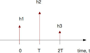
Lets us assume the channel to be a 3 tap multipath channel with spacing i.e.
Figure: Channel model (3 tap multipath)
In addition to the multipath channel, the received signal gets corrupted by noise , typically referred to as Additive White Gaussian Noise (AWGN). The values of the noise
follows the Gaussian probability distribution function,
with
mean and
variance .
The received signal is
, where
is the convolution operator.
MMSE Equalization
In Minimum Mean Square Error solution, for each sample time we would want to find a set of coefficients
which minimizes the error between the desired signal
and the equalized signal
, i.e.
,
where,
is the error at sample time
,
is column vector of dimension
storing the equalization coefficients,
is column vector of dimension
storing the received samples,
is the number of taps in the equalizer,
is the cross correlation between received sequence and input sequence ,
is the cross correlation between received sequence and input sequence and
is the auto-correlation of the received sequence.
For solving the Minimum Mean Square Error (MMSE) criterion, we need to find a set of coefficients which minimizes
.
Differentiation with respect to and equating to 0,
.
Simplifying,
,
Note :
a) is the variance of the input signal
b) (as there is no correlation between input signal and noise)
Simulation Model
Click here to download: Matlab/Octave script for computing BER for BPSK with 3 tap ISI channel with MMSE Equalization
The attached Matlab/Octave simulation script performs the following:
(a) Generation of random binary sequence
(b) BPSK modulation i.e bit 0 represented as -1 and bit 1 represented as +1
(c) Convolving the symbols with a 3-tap fixed fading channel.
(d) Adding White Gaussian Noise
(e) Computing the MMSE and ZF equalization filter at the receiver (with 7 taps in length)
(f) Demodulation and conversion to bits
(g) Counting the number of bit errors
(h) Repeating for multiple values of Eb/No
The simulation results are as shown in the plot below.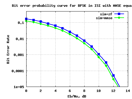
Figure: BER plot for BPSK in a 3 tap ISI channel with MMSE equalizer
Observations
1. Can see around 0.5dB gain with using MMSE equalizer
Reference
Complex to Real : Tutorial 26 – Filters, analog, digital and adaptive equalization
Hello Krishna,
first congratulations, you have a great site.
I have one question. When you use toeplitz([hAutoCorr([3:end]) zeros(1,2*K+1-L)], [ hAutoCorr([3:end]) zeros(1,2*K+1-L) ]), why is hAutoCorr and not just ht? I could not see it in your reference. Thanks.
@Mauro: hAutoCorr is the Ryy in the explanation. This is the autocorrelation of the received signal y, which reduces to the autocorrelation of the channel added with noise variance.
Helps?
Helps a lot, but, for example, if my channel vector size is 10 instead of 3.
e.g.: ht = [0.2 0.9 0.3 0.1 0.2 0.3 0.4 0.5 0.6 0.7];
How can i change the code? And how about the delay in yFilt_mmse = yFilt_mmse(K+2:end)?
Thanks.
@Mauro: Try playing with the filter delay with zero noise. Should be able to give some pointers
hello sir,hope ur fine ,I tried to plot the theoritical value in your (BER for BPSK in ISI channel with MMSE equalization ) but the theoritical value and simulated value dosent match with each other .is there anything i should do with the code ??.
and one more doubt sir . in ofdm system using qam modulation when plotted with ebno vs ber,the ebno value for 16 qam is less then the 64 qam.which modulation performs well ????
@bala:
1/ How did you get the theoretical value?
2/ Hmm… 16qam requires lower SNR than 64qam
https://dsplog.com/2012/01/01/symbol-error-rate-16qam-64qam-256qam/
https://dsplog.com/2008/07/08/compare-bpsk-qpsk-4pam-16qam-16psk-64qam-32psk/
do you have code for mmse-dfe equalizer?
can you guide me how to implement one. when i see the matlab help it gives a bunch of algorithms that can be used to implement one using equalize obj. I want to implement the most straight forward DFE equalizer.
@mepal: Will write up a post soon
@mepal: Will do a write up soon
@mepal: Had done a brief coding in the post, but did not do enough to make it into an article. One of the TODO’s….
waiting for ur new post !!!
@mepal: Me too 😉
sir i want your help for BER for BPSK in ISI channel with ML equalization.
@anuj: Will add soon
what can i do to equalize channel which has relatively longer tap than the equalizer taps ? thanks in advance
@berie: If the channel is relatively longer than the equalizer taps, then there can be residual inter symbol interference. Possibly a decision feedback equalizer can help to remove some of the interference.
hi …..do you know everybody that can help me write code in matlab for audio watermarking.
How about if I consider the undesired user as the undesired symbol in this case above.
what do you think about that?
@Basco: Possible. It all depends on how you model the system which you wish to analyze
Hi
Thanks for the simulation, very helpful.
I would like to know how you will use this mmse method to cancel interference from another user whilst detecting the desired signal.
Thanks in advance
@Basco: Thanks. Have not tried to model that case.
thank you..
sir, wil u please provide the code for qpsk modulation taking 256 fft size and 16 as training sequence.
@mayuri: Are you looking for an OFDM implementation?
Please take a look at http://www.dsplog.com/tag/ofdm
hi,
sir i want 2 knw how can we calculate mean square error of timing estimation using qpsk modulation and training sequenece?i mean to say that if i want to send a frame such that it has 256 bit fft size and training sequence is been used as cyclic prefix which is of 16 bit then how can i plot a graph of mean square error of timing and frequency estimation v/s snr?
@mayuri: Hmm… in general, one can find the difference between the desired and the obtained estimates, take the square and average over many realizations.
Is zero Padding necessary?
@Waheed: Zero padding at which point?
Hi Krishna, how are you? I just have this question, how do you exactly used K+2 for yFilt_zf = yFilt_zf(K+2:end);
Thank you.
@thavamaran: I guess, because the equalizer has a 3 tap delay, plus the delay of the channel. In practical systems, this delay needs to be estimated.
ok, I see. Two more questions
1. Why is actually c=R_yy^-1R_sy implemented as a convolution ?(the expression c_mmse = [inv(hM)*d.’].’; is a convolution due to toeplitz matrix)
I don’t quite understand why do you not multiply the matrices but convolve them?
2. Can the derivation of E(e(k))^2 be found in literature ? I’m looking for detailed mathematical background to this formula.
Best Regards and Thank you !
@joel:
1) Well, [inv(hM)*d.’].’ is not convolution. Its just the matrix multiplication as we derived.
2) Try Digital Communication by Proakis.
Further, I liked the material presented in http://www.complextoreal.com/chapters/filters.pdf (pages 20-30)
Hello,
can you please explain why are you using the toeplitz function ? You evaluate the E(hh^T) expression with following Matlab code :
hAutoCorr = conv(ht,fliplr(ht));
hM = toeplitz([hAutoCorr([3:end]) zeros(1,2*K+1-L)], [ hAutoCorr([3:end]) zeros(1,2*K+1-L) ]);
Can you please explain this ? Thank you !
Best Regards
@joel: Toeplitz matrices are used to represent convolution in a matrix multiplication form. Hope the brief post on toeplitz matrix @
https://dsplog.com/2007/04/21/using-toeplitz-matrices-in-matlab/ helps.
i want to ask???
i want create mmse equalizer but channel (ht) not ht=[0.3 0.9 0.2]
i want the channel is reylegh channel but not in the mimo system just create mmse equalizer with BPSK in reylegh channel (not mimo)
can you help me???
thank’s
fernando
@fernando: You can try changing ht to have Rayleigh components. Make sure that the receiver is also adjusted accordingly.
hi
i want to simulate doppler effect in ofdm simulation but i have some problem:
1-how i can with ifft command in matlab define separation sub-carrier frequency
2-how i can effecting doppler in my simulation
please if have any source or m-file insert your website
best regards
mhmdbehzad
@behzad: My replies:
1/ subcarrier spacing is controlled by the sampling clock and the number of points in the FFT. For examples, if the sampling clock is 20MHz and the FFT size is 64, the subcarrier spacing is 20MHz/64 = 312.5kHz
2/ I have not tried simulating doppler cases.
Drear Mr. Sankar,
I’m very thankful for your work. With your posts you have helped me several times. This post is excellent. I’ve lost several weeks trying to solve the problem by myself and haven’t succeeded. Thanks to your post it become more clear to me and I succeeded to make useful simulation. You are genius!
Thanks,
Jovan
@Jovan: Glad to be of help
glad to see it
sir pls help me in matlab implemantation we should requir to implemant the ifdma based paper so i need some help
@rajendrasingh: ifdma or ofdma? i have not discussed ofdma, but you can see some posts on OFDM @ https://dsplog.com/tag/ofdm/
please i need references and matlab code for channel estimation in ofdm system
would be grateful if u provide the needy
@siddarth: The post on OFDM BER in Rayleigh channel discuss that
https://dsplog.com/2008/08/26/ofdm-rayleigh-channel-ber-bpsk/
Hi ,Krishna i am impressed with the way you have simulated the BER of the MMSE and zero forcing equalkizers in presence of ISI.Would you please tell me what do you mean by taps .Is it the processing gain N?
Could you also tell me the System of transmission you have considered .Asynchronous symbol transmissions or synchronous?
Thank in advance
@Aristide:
a) In wireless transmissions, we get multiple copies of the transmitted signal at the receiver (due to reflections). The taps model that aspect.
b) Synchronous.
i am new to the mobile communication field and am just getting familiar with tools like matlab. i have a project at hand and i need to put up some thing before the month ends. pls can some help me out with the matlab source code? the topic of the research is the study of “the effect of ISI and equalisation on a mobile communication channel”. from my understanding so far, i need to plot some waveform with ISI and another with equalisation, compare them and hence state their effects from the two plots.the idea is there but doing this with matlab is a hell of a job especially for some new like me.i need help. thanks
@Gregg: Due to time constraints, I wont be able to help in the coding part. However, you can ask queries. I will try answer to the best of my knowledge
hello
i needthe matlab code for MMSE equalization in ofdm sysetm just to take idea how it works in OFDM ssytem.
or can u give u ur personal email address plz so tht i would contact wid u if i feel some problem during doing the code.
Regards
@sajib: You can find my details on https://dsplog.com/contact-us/
Hi,
Thanks for your code. It has been a great help.
I have since modified your code slightly to a 3 tap rayleigh fading channel (all taps follow Rayleigh fading, i.e. no longer a fixed 3 tap fading).
But I am not sure if it is correct. Any suggestions to go about verifying it?
@lim: Try simulating the BER vs Eb/N0 curve. Am not aware of any theoretical results to compare
please help me on DESIGN OF “RFMEMS SHUNT SWITCHS ” IN MAT LAB
@balakrishna: Sorry, am not aware of RFMEMS shunt switches
your script is really appreciable sir. it is really helpful to me
1) i want to implement MMSE equalization in OFDM. can u help me on this sir
2) actually i want to know where should i aplly the equalizer in ofdm. either just before removing cyclic prefix or after takeing FFT.
plz help sir
@bhasker: Remove cyclic prefix, take FFT. You can see an example BER for BPSK in OFDM in AWGN @ https://dsplog.com/2008/06/10/ofdm-bpsk-bit-error/
thanks for your your graet work
please I study for my master in frequency synchronization in mimo ofdm system but i have problem with the matlab code to simulate to find out if estimation of the CFO on one path is affected by the CFO values of the adjacent paths and examine the estimator accuracy in term of its mean and variance
please help me it’s urgent and necessary
f_max = f_Tofdm/(M_sub*T_s); % f_max =maximal Doppler frequency (Hz),M_sub*T_s = OFDM Symbol period (sec),
%f_ndopp = f_max*M_sub*T_s % Normalized Maximum Doppler Spread Freq.
% Area parameter
% ra Rural Area
% tu Typical Urban
% bu Bad Urban
% ht Hilly Terrain
% no no fading
AREA = ‘no’ ;
% start simulation loops
for ee = 1 : length(EcNo)
ee
[theo_fo_var, rfo_var, rfo] = FOE_mimo_fading(EcNo(ee), tfo_array, NTX, NRX, M_sub, N, f_max, AREA, T_s, model, L);
plot_theo_fo_var(:,:,ee)=theo_fo_var;
plot_rfo_var(:,:,ee)=rfo_var;
plot_theo_rfo(:,:,ee)=tfo_array;
plot_rfo(:,:,ee)=rfo;
end
% plot results
for ii_tx = 1 : NTX
for ii_rx = 1 : NRX
% rearrange array order for easier plotting
vect_plot_theo_rfo = permute(plot_theo_rfo(ii_tx,ii_rx, , [2 3 1]);
vect_plot_rfo= permute(plot_rfo(ii_tx,ii_rx, , [2 3 1] ) ;
vect_plot_theo_fo_var= permute(plot_theo_fo_var(ii_tx,ii_rx,:),[2 3 1]);
vect_plot_rfo_var= permute(plot_rfo_var(ii_tx,ii_rx, , [2 3 1]);
%plot mean
figure;
plot(EcNo, vect_plot_theo_rfo, ‘:’ , ‘Linewidth’,2) ;
hold;
plot(EcNo, vect_plot_rfo,’o-’,’MarkerSize’ , 6,’Linewidth’, 1) ;
grid on;
t_str=sprintf(’New_ Theo and Est Freq Offset %s M=%d N=%d %dx%d path:tx%d-rx%d fo=%1.3f’,AREA,M_sub,N,NTX,NRX,ii_tx,ii_rx,tfo_array(ii_tx,ii_rx));
title(t_str);
xlabel(’EcNo SNR range and step (in dB)’);
ylabel(’Norm Freq Offset’) ;
legend(’Theo’,’Est’,’Location’,’Northeast’);
% save graph
fstr=sprintf(’new_m%d_%dx%dp%d%d_%s’,M_sub,NTX,NRX,ii_tx,ii_rx,AREA);
hgsave(fstr);
% plot variance
figure;
semilogy(EcNo, vect_plot_theo_fo_var,’:’,’Linewidth’,2);
hold;
semilogy(EcNo, vect_plot_rfo_var,’o-’,’MarkerSize’,6,’Linewidth’,1);
grid on;
grid minor;
t_str=sprintf(’New_ Est Var and CRLB %s M=%d N=%d %dx%d path:tx%d-rx%d fo=%1.3f’,AREA,M_sub,N,NTX,NRX,ii_tx,ii_rx,tfo_array(ii_tx,ii_rx));
title(t_str);
xlabel(’EcNo (in dB)’);
ylabel(’Variance’);
legend(’CRLB’,’Est’,’Location’,’Northeast’);
% save graph
fstr=sprintf(’new_y%d_%dx%dp%d%d_%s’,M_sub,NTX,NRX,ii_tx,ii_rx, AREA) ;
hgsave(fstr);
end
end
% rename variables for export
new_plot_theo_fo_var=plot_theo_fo_var;
new_plot_rfo_var=plot_rfo_var ;
new_plot_theo_rfo=plot_theo_rfo;
new_plot_rfo=plot_rfo;
% save all variables
fstr=sprintf(’new_f%d_%dx%d_%s.mat’,M_sub,NTX,NRX,AREA);
save(fstr);
% save variables for plotting
fstr=sprintf(’new_p%d_%dx%d_%s.mat’,M_sub,NTX,NRX,AREA);
save(fstr,’new_plot_theo_fo_var’,’new_plot_rfo_var’,’new_plot_theo_rfo’,’new_plot_theo_rfo’);
% end of file
@eng_dina: How are you modeling the CFO for MIMO systems?
If all the chains have a common RF clock, then all the chains will have similar CFO and the estimate from all the chains can be combined to improve the accuracy of the CFO estimation.
If the chains have independent RF clock, then we need to estimate CFO on each chain independently.
Hi Krishna,
I hope you are doing well. I am simulating 16 QAM in a Rayleigh channel and am trying to compute the SER(& BER). I need to verify my results using the theoretical formula. Can you kindly tell me the formula of SER for 16 QAM in Rayleigh channel?
I shall be grateful
Thanking in advance,
@mesange: I have not discussed 16QAM in Rayleigh channel case. However, you can discussion on
a) Symbol error rate for 16QAM in AWGN
https://dsplog.com/2007/12/09/symbol-error-rate-for-16-qam/
b) Bit error rate for 16QAM in AWGN assuming Gray coded bit mapping
https://dsplog.com/2008/06/05/16qam-bit-error-gray-mapping/
c) BER for BPSK in Rayleigh channel
https://dsplog.com/2008/08/10/ber-bpsk-rayleigh-channel/
Hope you will be able to extend these results to Rayleigh channel 16QAM case. Good luck.
Thanks for this post – really 🙂
Hi
I am not able to open the code file, is there any problem.
Please check:
Thanks
@Abrar: I fixed that. Thanks for pointing out.