Update: Correction in Matlab code for raised cosine filter

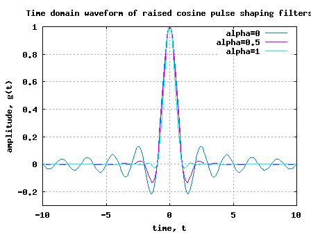
Thanks to the keen observation by Mr. Phan Minh Hoang, I was notified that the Matlab/Octave scripts provided along with the topic raised cosine filtering was not behaving properly.

Reason: I was not taking care of the division by zero when creating the raised cosine filter taps. 🙁 Continue reading “Update: Correction in Matlab code for raised cosine filter”

Eye diagram with raised cosine filtering

We have discussed about probable transmit pulse shaping filter and have observed that raised cosine filtering filtering allows a simpler implementation, albeit at the cost of increased bandwidth. Let us know understand the eye diagram, which is a useful graphical tool to quantify the degradation of the signal due to filtering.

Eye diagram

An eye diagram is generated in an oscilloscope operating in the persistence mode by observing the output of the filter with the symbol timing serving as the trigger. The observation window can be set as 2 times the symbol period. (Refer. Section 5.1.3 in [DIG-COMM-BARRY-LEE-MESSERSCHMITT]).

Continue reading “Eye diagram with raised cosine filtering”

Raised cosine filter for transmit pulse shaping

In the previous post on transmit filtering using Nyquist pulse, we had briefly learned that the information symbol with a symbol period can be transmitted without inter symbol interference (ISI) by using Nyquist pulse,

.

The resultant waveform is ideally bandlimited to frequencies from Hz to Hz.

However, in typical transmission schemes, we do not hear of pulse shaping using sinc() filters. Rather, pulse shaping using raised cosine filter is frequently used. In this post, objective is to understand the motivation behind using raised cosine filtering for pulse shaping.

Continue reading “Raised cosine filter for transmit pulse shaping”