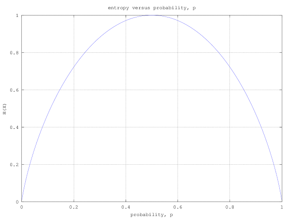
Question 15 on communication from GATE (Graduate Aptitude Test in Engineering) 2012 Electronics and Communication Engineering paper.
Tag: Communication
GATE-2012 ECE Q2 (communication)
Question 52 on communication from GATE (Graduate Aptitude Test in Engineering) 2012 Electronics and Communication Engineering paper.
Q2. The power spectral density of a real process}) for positive frequencies is shown below. The values of
for positive frequencies is shown below. The values of \]}) and
and \]\|}) , respectively are
, respectively are
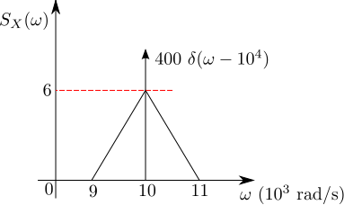
(A) 
(B) 
(C) })
(D) })
![]()
Solution
For a wide sense stationary function, the auto-correlation with delay is defined as,
From the Weiner-Kinchin theorem, the auto-correlation function and power spectral density
are Fourier Transform pairs, i.e.
Expressing in terms of , where
.
When the delay , the above equations simplifies to
.
Applying this to the problem at hand,
.
Further, since the power spectral density does not have any dc component, the mean of the signal
Based on the above, the right choice is (B)
References
[1] GATE Examination Question Papers [Previous Years] from Indian Institute of Technology, Madras http://gate.iitm.ac.in/gateqps/2012/ec.pdf
[3] Wide sense stationary function
[4] Auto-correlation
GATE-2012 ECE Q39 (communication)
Question 39 on communication from GATE (Graduate Aptitude Test in Engineering) 2012 Electronics and Communication Engineering paper.
Q39. The signal }) as shown is applied both to a phase modulator (with
as shown is applied both to a phase modulator (with  as the phase constant) and a frequency modulator (with
  as the frequency constant) having the same carrier frequency.

The ratio  }) for the same maximum phase deviation is,
for the same maximum phase deviation is,
(A) 
(B) 
(C) 
(D) 
![]()
Solution
To answer this question, let us understand basics of Frequency modulation and Phase modulation. Am referring to the discussion in Section 10 of Electronic Communication, 4th Edition, Dennis Roddy, John Coolen (buy from Amazon.com, buy from Flipkart.com).
Frequency Modulation
In frequency modulation, the modulation signal will cause a change in the instantaneous carrier frequency and is related as
where
is the frequency deviation constant expressed in hertz/volt (Hz/V) and
is the carrier frequency in Hz.
The angular velocity radians per second.
Since the rate of change of phase is the angular velocity,
and so, the instantaneous phase is
.
The frequency modulated carrier signal is
Phase modulation
In phase modulation, the modulation signal will cause a change in phase and the instantaneous phase is
where
is the phase deviation constant expressed in radians/volt and
is the carrier frequency in radians per second.
The phase modulated carrier signal is
.
Now, applying the above equations to solve the problem :
In frequency modulation case, the maximum phase deviation happens when the term hits the maximum.
In phase modulation case, the maximum phase deviation happens when the term hits the maximum.
.
The ratio is,
and so,
Based on the above, the right choice is (B)
References
[1] GATE Examination Question Papers [Previous Years] from Indian Institute of Technology, Madras http://gate.iitm.ac.in/gateqps/2012/ec.pdf
[2] Electronic Communication, 4th Edition, Dennis Roddy, John Coolen (buy from Amazon.com, buy from Flipkart.com).
GATE-2012 ECE Q38 (communication)
Question 38 on Communication from GATE (Graduate Aptitude Test in Engineering) 2012 Electronics and Communication Engineering paper.
Q38. A binary symmetric channel (BSC) has a transition probability of 1/8. If the binary transmit symbol X is such that P(X=0)=9/10, then the probability of error for an optimum receiver will be
(A) 7/80
(B) 63/80
(C) 9/10
(D) 1/10
![]()
Solution
The solution to the problem seem deceptively reasonably simple. Quoting from the Wiki entry on Binary Symmetric Channel
A binary symmetric channel (or BSC) is a common communications channel model used in coding theory and information theory. In this model, a transmitter wishes to send a bit (a zero or a one), and the receiver receives a bit. It is assumed that the bit is usually transmitted correctly, but that it will be “flipped” with a small probability (the “crossover probability”). This channel is used frequently in information theory because it is one of the simplest channels to analyze.”
In our example, the transition probability i.e probability of transition (i.e. 1 becoming 0 or 0 becoming 1) for each alphabet is given as 1/8. probability of correct transmission, for each alphabet is given as 1/8 (the probability of incorrect transition is 7/8).
The transition probability diagram with the above data can be drawn as,
![]()
Figure : Transition probability diagram for a binary symmetric channel
The probability of the source alphabets are,
.
The transition probability when is :
.
Similarly the transition probability when is :
.
The received alphabet not equal to the transmitted alphabet is,
.
Hold on, we are not done yet.
Update (9th Nov 2012):
The above gives the probability that the received symbol is not equal to the transmitted symbol, and not the probability of error for an optimum detector. Thanks to Mr. Raghava GD who rightly pointed out in the comment section that – “the calculation that you did just gives the probability of receiving the bit erroneously and it doesn’t tell anything about the probability of error for an optimum decoder.”
After digesting his comments, and referring from Section of 1.2 of Chapter 1 of Prof. John M. Cioffi’s book ,
Consider the channel model which produces a discrete vector output for a discrete vector input. The detector chooses a message from all possible messages
transmit vectors. The channel input vector
results in a corresponding channel output vector
. The decision device translates the received vector
to an estimate of the transmitted vector
and a decoder converts
to the estimate of the message vector
.

Figure : Vector channel model (Reference : Figure 1.13 in Chapter 1 of Prof. John M. Cioffi’s book)
The probability of error is defined as,
.
Correspondingly, the probability of being correct is,
.
The optimum detector chooses to minimize the probability of error
or equivalently maximize
.
The probability of making the correct decision , given the received vector
is
.
The above quantity known as the posteriori probability, and an optimum decision device will try to maximize the above quantity. The Maximum a Posteriori Detector (MAP), is defined as the detector that chooses the index to maximize the a posterior probability
given the received vector
.
Using Bayes therorem, the posterior probability can be written in terms of prior probability and the channel transition probability
,
.
Note :
The term is a constant and can be ignored when trying to maximize the posterior probability
.
The MAP detection rule is,
.
Note :
This is discussed briefly in Chapter 5.1.3 The Optimum Detector in Digital Communications, Fourth edition John G. Proakis (buy from Amazon.com, buy from Flipkart.com)
Applying the MAP detection rule to the problem at hand :
We have two candidates 0 and 1 for the source message i.e
a) ,
b) modulator is a pass through i.e and
c) received symbol can be 0 or 1.
The goal is to make decision rule on the observed received symbol .
Applying MAP detection rule,
.
.
In both the cases i.e when received symbol , the optimum MAP detection rule suggest that the estimated message symbol is
.
Intuitively, this makes sense : given that , a receiver will be better of assuming that the transmitted symbol is always 0. With this, the probability of making an error in the decision is
.
Matlab example
clear all; close all;
% number of observations
N = 10^5;
% generating x with p(x=0) = 9/10, p(x=1) = 1/10
x = (rand(1,N) > 9/10);
% generating c with p(c=0) = 1/8, p(c=1) = 7/8
c = (rand(1,N) < 7/8);
% binary symmetric channel
y = mod(x+c,2);
xhat = 0;
% counting errors
nErr    = size(find(xhat-x),2);
errProb = nErr/N
Based on the above, the right choice is (D) 1/10.
References
[1] GATE Examination Question Papers [Previous Years] from Indian Institute of Technology, Madras http://gate.iitm.ac.in/gateqps/2012/ec.pdf
[2] Wiki entry on Binary Symmetric Channel http://en.wikipedia.org/wiki/Binary_symmetric_channel
[3] Chapter 1 of Prof. John M. Cioffi’s book
[4] Wiki entry on posteriori probability
[5] Wiki entry on Bayes therorem
[6] Digital Communications, Fourth edition John G. Proakis (buy from Amazon.com, buy from Flipkart.com)
GATE-2012 ECE Q3 (communication)
Question 3 on Communication from GATE (Graduate Aptitude Test in Engineering) 2012 Electronics and Communication Engineering paper.
Q3. In a baseband communications link, frequencies upto 3500Hz are used for signalling. Using a raised cosine pulse with 75% excess bandwidth and for no inter-symbol interference, the maximum possible signaling rate in symbols per second is,
(A) 1750
(B) 2625
(C) 4000
(D) 5250
![]()
Solution
To answer this question, am using contents from Section 5.1 of Digital Communication, third edition, John R. Barry, Edward A. Lee, David G. Messerschmitt (buy from Amazon.com, buy from Flipkart.com).
Let us first try to understand the minimum bandwidth required to transmit the signal at symbol rate
with no inter symbol interference (ISI).
The transmitted signal is,
,
where
is the
transmitted data symbols,
is the symbol rate and
is the pulse shape.
The sampled signal is,
.
Decomposing the above equation into two parts,
.
The first term is the desired signal and the second term contributes to inter symbol interference.
To ensure that there is no intersymbol interference, the sampled pulse shape should be
.
Taking Fourier transform, this translates to the following criterion
.
Note : For convenience, take
.
Note :
The proof for this is discussed in bit more detail in Section 9.2 of Digital Communications, 4th edition John G. Proakis (buy from Amazon.com, buy from Flipkart.com)
Let us assume that pulse shape has a bandwidth
. There are three cases to check
i) When :
In this case, the plot of will have non-overlapping replicas of the spectrum
separated by
and there is no choice to meet the
criterion.
ii) When :
There exists one candidate meeting the criterion,
.
The corresponding pulse shape is
.
Alternately, this can be stated as – for a given single sided bandwidth , the maximum symbol rate which can be achieved for ISI free transmission is
. To meet this, the pulse shape
has to be a sinc function. Typically usage of the sinc function is not preferred as its tails decay very slowly and a small timing error in the demodulator will result in an infinite series of inter symbol interference components.
iii) When
In this case consists of overlapping spectrum of
separated by
and there exists multiple choices meeting the
criterion.
A commonly used pulse shaping filter satisfying the criterion while having a faster decay is the raised cosine filters having the following equation,
.
The frequency response is,
.
With a raised cosine pulse shape, the bandwidth is larger than the minimum required pulse shape and is related as,
.
Then term is called the excess bandwidth factor. For example,
translates to 75% excess bandwidth
translates to 100% excess bandwidth
, the raised cosine pulse shape reduces to sinc pulse shape.
In our question,
and
and the goal is to find the maximum possible symbol rate
.
Substituting for ,
and solving for
,
.
Matlab example
% script for plotting the time and frequency response of raised cosine pulse shape
% filter with
% a) alpha = 0 (sinc pulse)
% b) alpha = 3/4
%
clear all; close all;

fs = 10;
% defining the sinc filter
sincNum = sin(pi*[-fs:1/fs:fs]); % numerator of the sinc function
sincDen = (pi*[-fs:1/fs:fs]); % denominator of the sinc function
sincDenZero = find(abs(sincDen) < 10^-10);
sincOp = sincNum./sincDen;
sincOp(sincDenZero) = 1; % sin(pix/(pix) =1 for x =0

alpha = 0;
cosNum = cos(alpha*pi*[-fs:1/fs:fs]);
cosDen = (1-(2*alpha*[-fs:1/fs:fs]).^2);
cosDenZero = find(abs(cosDen);
cosOp(cosDenZero) = pi/4;
gt_alpha0 = sincOp.*cosOp;
GF_alpha0 = (1/fs)*fft(gt_alpha0,1024);

alpha = 0.75;
cosNum = cos(alpha*pi*[-fs:1/fs:fs]);
cosDen = (1-(2*alpha*[-fs:1/fs:fs]).^2);
cosDenZero = find(abs(cosDen);
cosOp(cosDenZero) = pi/4;
gt_alpha0 = sincOp.*cosOp;
GF_alpha0 = (1/fs)*fft(gt_alpha0,1024);

alpha = 0.75;
cosNum = cos(alpha*pi*[-fs:1/fs:fs]);
cosDen = (1-(2*alpha*[-fs:1/fs:fs]).^2);
cosDenZero = find(abs(cosDen)
cosOp(cosDenZero) = pi/4;
gt_alpha_p75 = sincOp.*cosOp;
GF_alpha_p75 = (1/fs)*fft(gt_alpha_p75,1024);

Figure : Time domain plot

Figure : Frequency domain plot
Based on the above, the right choice is (C) 4000 symbols per second.
References
[1] GATE Examination Question Papers [Previous Years] from Indian Institute of Technology, Madras http://gate.iitm.ac.in/gateqps/2012/ec.pdf
[2] Digital Communication, Third edition, John R. Barry, Edward A. Lee, David G. Messerschmitt (buy from Amazon.com, buy from Flipkart.com)
[3] Digital Communications, Fourth edition John G. Proakis (buy from Amazon.com, buy from Flipkart.com)