In the past, we had discussed BER for BPSK in flat fading Rayleigh channel. In this post, lets discuss a frequency selective channel with the use of Zero Forcing (ZF) equalization to compensate for the inter symbol interference (ISI). For simplifying the discussion, we will assume that there is no pulse shaping at the transmitter. The ISI channel is assumed to be a fixed 3 tap channel.
Transmit symbol
Let the transmit symbols be modeled as
, where
is the symbol period,
is the symbol to transmit,
is the transmit filter,
is the symbol index and
is the output waveform.
For simplicity, lets assume that the transmit pulse shaping filter is not present, i.e .
So the transmit symbols can be modeled by the discrete time equivalent

Figure: Transmit symbols
Channel Model
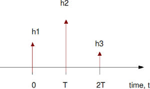
Lets us assume the channel to be a 3 tap multipath channel with spacing i.e.
Figure: Channel model (3 tap multipath)
In addition to the multipath channel, the received signal gets corrupted by noise , typically referred to as Additive White Gaussian Noise (AWGN). The values of the noise
follows the Gaussian probability distribution function,
with
mean and
variance .
The received signal is
, where
is the convolution operator.
Zero Forcing Equalization
Objective of Zero Forcing Equalization is to find a set of filter coefficients which can make
.
After equalization
.
Note:
The term causes noise amplification resulting poorer bit error rate performance.
Deriving the equalization coefficients
From the post on toeplitz matrix,we know that convolution operation can be represented as matrix multiplication.
% Matlab code for using Toeplitz matrix for convolution
clear all
x = [1:3];
h = [4:6];
xM = toeplitz([x zeros(1,length(h)-1) ], [x(1) zeros(1,length(h)-1) ]);
y1 = xM*h';
y2 = conv(x,h);
diff = y1'-y2
diff = [  0   0   0   0   0 ]
Using similar matrix algebra and assuming that the coefficients has 3 taps, the equation
can be equivalently represented as,
Solving for , we have
.
If we assume that has 5 taps,
Solving for , we have
.
Example
% Assuming a 3 tap channel as follows
ht = [0.2 0.9 0.3];
L = length(ht);
kk = 1;
hM = toeplitz([ht([2:end]) zeros(1,2*kk+1-L+1)], [ ht([2:-1:1]) zeros(1,2*kk+1-L+1) ]);
d  = zeros(1,2*kk+1);
d(kk+1) = 1;
c  = [inv(hM)*d.'].';
The frequency response of the channel and the equalizer
are shown below:
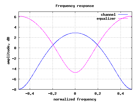
Figure: Frequency response of the channel and the equalizer
Simulation Model
Click here to download: Matlab/Octave script for computing BER for BPSK with 3 tap ISI channel with Zero Forcing Equalization
The attached Matlab/Octave simulation script performs the following:
(a) Generation of random binary sequence
(b) BPSK modulation i.e bit 0 represented as -1 and bit 1 represented as +1
(c) Convolving the symbols with a 3-tap fixed fading channel.
(d) Adding White Gaussian Noise
(e) Computing the equalization filter at the receiver – the equalization filter is 3, 5, 7, 9 taps in length
(f) Demodulation and conversion to bits
(g) Counting the number of bit errors
(h) Repeating for multiple values of Eb/No
The simulation results are as shown in the plot below.
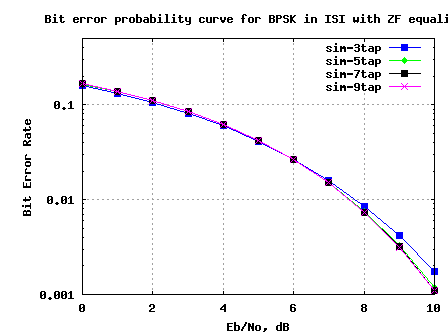
Figure: BER plot for BPSK in a 3 tap ISI channel with Zero Forcing equalizer
Observations
1. Increasing the equalizer tap length from 3 to 5 showed reasonable performance improvement.
2. Diminishing returns from improving the equalizer tap length above 5.
3. The results are poorer compared to the AWGN no multipath results. This is due to the noise amplification (see the frequency response above) by the zero forcing equalization filter.
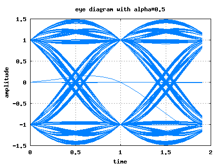
Next step is to discuss the zero forcing equalizer in the presence of transmit pulse shaping and then move on to minimum mean square error equalizer.

sir,
i m doing a project on interference mitigation in UWB channel. I hav choose transmitted reference receiver to mitigate interference. hav not able to model the channel..:-( m i proceeding in a right way??
plz sir help me…
@chayanika: For modeling the channel, one can start of with a simple AWGN noise model and later one can add multipath to it. For modeling interference, one need to idea of how is interfering – Is it another UWB transmitter operating in the same frequency?
Have you developed any code for co-channel interfernce in MIMO channel
@Dibyani: sorry, no
hello mr
realllllllllllllllly Very nice work sir!!
can you help me for use that in mimo channel (alamouti method)?
how shoul I do in combiner level?I should use conv ? or multiply? :((
plz help me I am really need it :'(
@Amire: Typically, when dealing with MIMO channel (especially using OFDM), it is a convolution in the time domain. However, assuming that the channel is contained with in the cyclic prefix, the effect of channel in frequency domain is a single mutliplier with amplitude/phase values.
My question is related to MF part.
If we perform pulse shaping g(t) at the transmitter then the overall pulse shape is g(t)*h(t) and the received waveform would be
r(t) = a_k( g(t)*h(t) ) + n(t)
at the receiver the MF would be matched to (g(t)*h(t)) followed by a sampler and LE.
but in this MATLAB CODE setting the , the first thing i see is LE……(which is confusing.)
followed by another convolution (about which you have commented that its there to take care of pulse shaping done at TX which does not exist in this example and is therefore redundant)
can you plz explain this.
@mepal:
Thanks for pointing that out. In this simulation, have not used any pulse shaping. The code which has the comment stating it is matched filtering is indeed doing the equalization part.
Another comment which I have is : if we have inter symbol interference, then it is preferable to do equalization first and then do the matched filtering. Agree?
Hi,
Please I need some explanation on the first two lines of the matches filter part;specifically,why you used kk+2
yFilt = yFilt(kk+2:end);
Thanks.
@Sylva: The kk+2 is to ignore the first few samples caused by the delay of the filter.
Hi,
Do you have the theoritical BER for zero forcing equalization and MMSE equalization?
Thanks
Siva
@Siva: Hmm.. no
Hi Krishna Sankar,
Can you explain a little bit more about the ‘Matched Filter’ part?
yFilt = yFilt(kk+2:end);
yFilt = conv(yFilt,ones(1,1)); % convolution
ySamp = yFilt(1:1:N); % sampling at time T
Thank you.
@Binh: Don’t think we need the matched filter part given that we have not put any pulse shaping in the transmitter section. May have been inherited from some existing code…
Could you please let me know the purpose of this step? Why are we performing convolution with 1 at the receiver?
yFilt = conv(y,c);
yFilt1 = yFilt(kk+2:end);
yFilt = conv(yFilt,ones(1,1)); % convolution
ySamp = yFilt(1:1:N); % sampling at time T
Thanks.
@Siva: The last two line may have been inherited from existing code which had pulse shaping in the transmitter. Sorry about that.
Thank you a lot all are really help full!
I will be happy if any one help me using LMS for MIMO systems
@Fantaye: Guess, you want to use LMS for channel tracking?
Hi Mr.Krishna,
For a MIMO system, how do I model an ISI channel? Meaning do I sum the impulse responses for the various paths from antenna i to antenna j and denote it as a single co efficient in the H matrix as h(ji)?
And so how do I perform ZF-SIC for the same case?
@vsk: In a MIMO ISI case, convolve each transmit stream with the channel seen from each transmit stream to receive antenna.
For eg, if
h11 – channel between transmit antenna 1 to receive antenna 1
h12 – channel between transmit antenna 2 to receive antenna 1
h21 – channel between transmit antenna 1 to receive antenna 2
h22 – channel between transmit antenna 2 to receive antenna 2
The received symbol on receive antenna 1
y1 = conv(h11,x1) + conv(h12,x2) + n1
y2 = conv(h21,x1) + conv(h22,x2) + n2
and x1, x2 are transmit symbols from antenna 1 and 2 respectively.
Do NOT sum all the impulse response and represent them as a single value.
Hi i have a question regarding the ZF-equlization, what if the desired tap is at the last position?
h = [0.3 0.1 0.9]. I tried to change the code but i could not.
@Ali: Try changing the creation of the Toeplitz matrix such that h3 comes in the diagonal term…
Can you please explain why hM
hM = toeplitz([ht([2:end]) zeros(1,2*kk+1-L+1)], [ ht([2:-1:1]) zeros(1,2*kk+1-L+1) ])
for kk=1 is
hM =
0.9000 0.2000 0
0.3000 0.9000 0.2000
0 0.3000 0.9000
instead of
0.2000 0 0
0.9000 0.2000 0
0.3000 0.9000 0.2000
0 0.3000 0.9000
0 0 0.3000
given h0=0.2 , h1=0.9 , h2=0.3
when we perform convolution one of the signals is flipped at t=0.
this means that the flipped signal should be
h(-2) = 0.3
h(-1) = 0.9
h(0) = 0.2
so the convolution matrix should look like the second matrix.
(i used convmtx(ht’,2*kk+1) to generate the 2nd matrix)
kindly let me know what point i m missing here.
@mepal: the end goal is to make conv(c,ht) = impulse.
i have one more question here:
we want to make the cascade of channel and equalizer equivalent to a single impulse(incase of ZF LE).
How is this different from Partial Response Target Equalization (PRTE).
In PRTE one defines a target and derive optimal equalizer by minimizing MSE. So there is an optimality criterion involved in the derivation of PTRE but apart from that we desire to have the conv(c,ht)=target .
Can we comment that MMSE LE is same as PTRE (both r derived based on minimizing MSE)?
Is the above observation correct?
@mepal: Hmm… I have not studied the topic PRTE, so can’t really comment. However, your train of thoughts sound reasonable.
Hiii Mr.Krishna
Thank you for ur post, that is help me so much. That is time invariant channel???
@Newbie: A channel whose taps do not vary with time is a time invariant channel 🙂
Hi Krishna,
One question about the channel coeffecients. They are real number as I we find here. But in case of Rayleigh channel they are complex where both real are imaginary parts are samples from Gaussain distribution. My question is if we consider a static ISI channel with complex coeffcients, is there anything wrong with it?Since the co-efficients refer to the gain of each tap, I feel complex values are also possible where the imaginary parts refers to the phase.
Waiting for your response.
Ahmed
@Ahmed: Complex channel coefficients are also possible
Hi Krishna,
Request you to please explain the below mentioned part of your code.
K=4; What is the significance of this K and why is it equal to 4?
for kk = 1:K
L = length(ht);
hM = toeplitz([ht([2:end]) zeros(1,2*kk+1-L+1)], [ ht([2:-1:1]) zeros(1,2*kk+1-L+1) ]);
d = zeros(1,2*kk+1);
d(kk+1) = 1;
c = [inv(hM)*d.’].’;
% mathched filter
yFilt = conv(y,c);
yFilt = yFilt(kk+2:end);
yFilt = conv(yFilt,ones(1,1)); % convolution
ySamp = yFilt(1:1:N); % sampling at time T
Can we not perform the above operations using just conv or filter functions in Matlab?
Please provide your comments.
Thanks
Ishwinder
K = 4 equalizers. Inside the loop, the length of the equalizer is chosen by 2*kk+1, where kk = 1:4 (3,5,7,9).
@Loic: hmm… ok
@Ishwinder: I wanted to compare 3tap/5tap/7tap/9tap equalization case
k = 1 –> 3 tap; k = 2–> 5 tap and so on
hello, Krishna Sankar, I have a question on ZF for ISI channel.
As your example, I have ISI channel with three taps [h1 h2 h3], then the signal [S1 S2 S3 S4 S5 S6 S7 …] passes through the channel. At the receiver, the received signal denoted by [R1 R2 R3 R4 R5 R6 R7…]. For example, I want to detect symbol R6, we can readily find that R6=h1*S6+h2*S5+h3*S4, then this signal passes through ZF equalizer with coefficients [C1 C2 C3]. Then the estimated symbol for R6 will be :
^R6=C1*R6+C2*R5+C3*R4=C1h1S6+(C1h2+C1h1)S5+(C1h3+C2h2+C3h1)S4+(C2h3+C3h2)S3+c3h3S2
Why it’s different from your derivation results. Can you tell where I’m wrong.
@Andrew: Its a convolution operation.
please send me multi-user detectors in ds-cdma
@j.ravindra babu: Sorry, I do not know
hi sir
plz help on code for multiuser detection in cdma
@CHANDU: In CDMA, each user is assigned a code. Run the received samples through a filter matched to each code
It’s a useful one for me
@Ananthi: Thanks
Thanks for your post!
When I saw some old posts, many red “X” appear where the formula or symbol should be. How can I solve it ? Is something wrong with my browser?
@rajesh: Can you please list the posts where you saw this error. This is not expected. Anyhow once you give the list, I will take a look.
hi,
In your code,
ht = [0.4 0.9 0.3];
I tried another value like ht = [0.6 0.9 0.3];
then BER increased dramatically, it doesn;t make sense
Can you tell me what’s the problem? THX
Thanks for your post!
When I saw some old posts, many red “X” appear where the formula or symbol should be. How can I solve it ? Is something wrong with my browser?
Thanks A Lot For This
Hi Krishna
Thank you for very nice post
May I ask you about the basic question
From the script below
10^(-Eb_N0_dB(ii)/20)*n; % additive white gaussian noise
I know that
10log10(A_power) = A_power dB —- (1)
20log10(A_voltage) = A_voltage dB —– (2)
when we try to convert Eb_N0 into dB we use formula (1)
10log10(Eb_N0) = Eb_N0_dB
Why does the division factor equal to 20 ?
Thanks
@Puripong: We want to convert scale the noise voltage by a factor corresponding to Eb_N0_dB. To convert dB to voltage we have the 1/20 term (as you have pointed out in (2)). Helps?
You mean….
We want to convert Eb_N0_dB into noise voltage.
sqrt(voltage) = Eb_N0_dB
voltage = Eb_N0_dB^2
10log10(Eb_N0_dB^2) = 20log10(Eb_N0_dB)
So, we have the division factor equal to 20
Ohhh, Surely I missed.
Thank you very much
@Puripong: Glad to help
Very nice work , AMAZING
Keep Goning
@Ayhem: Thanks 🙂
Fantastic work! really. Can’t wait for MMSE equalization (I think that would be next)
Krishna, would you please help me with the two questions I have with respect to your posts on OFDM and EGC. I have provided the link below
For OFDM:
https://dsplog.com/2008/08/26/ofdm-rayleigh-channel-ber-bpsk/#comment-15910
For EGC:
https://dsplog.com/2008/09/19/equal-gain-combining/#comment-16350
I’d appreciate your help
@communications_engineer: Thanks. Hope my reply to both the comments addressed some of your concerns. Good luck.
Wow~~ New topic, I like it~!
thank you so much!!