Following discussion of bit error rate (BER) for BPSK and bit error rate for FSK, it may be interesting to move on to discuss a higher order constellation such as Pulse Amplitude Modulation (PAM).
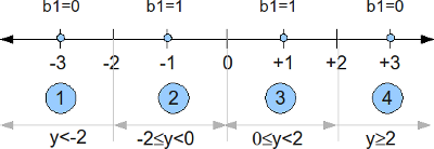
Consider that the alphabets used for a 4-PAM is (Refer example 5-34 in [DIG-COMM-BARRY-LEE-MESSERSCHMITT]
).
The average energy of the constellation assuming all the alphabets are equally likely is,
.
The constellation plot for a 4-PAM signal after normalization can be as shown below.

Figure: Constellation plot for 4 PAM modulation
Channel Model
Now comes the interesting task – analysis of symbol error probability for the modulation scheme in additive white Gaussian noise condition. The noise follows the Gaussian probability distribution function,
with
and
.
Computing the symbol error rate
Using the derivation provided in Section 5.2.1 of [COMM-PROAKIS] as reference:
The received signal can be
or
or
or
.
Let us first consider the case was transmitted.
The conditional probability distribution function (PDF) of given
was transmitted is :
.

Figure: Probability distribution function when the alphabet +3 is sent
Using midway point between +1 and +3 as the detection threshold, i.e. for received signal .
With this threshold, the probability of error given is transmitted is (the area in blue region):
.
Note: The complementary error function, .
Given that the constellation of +3 and -3 is symmetric, it is reasonably intuitive that the probability of error given is transmitted is also,
.
Case where is transmitted
The conditional probability distribution function (PDF) of given
was transmitted is :
.

Figure: Probability distribution function when the alphabet +1 is sent
The probability of error given is transmitted is (the area in green and red region):
Given that the constellation for +1 and -1 is symmetric, it is reasonably intuitive that the probability of error given is transmitted is also,
.
Total probability of symbol error
Given that all the alphabets are equally likely, the total probability of symbol error is,
.
Assuming, and
,
are equally probable i.e.
, the symbol error probability is,
Simulation Model
The Matlab/Octave script for generating a 4-PAM transmission, pass it through additive white Gaussian noise and demoduation at the receiver will be useful for understanding the concept further. The symbol error rate plots obtained from simulations compare well with the theoretical derivations.
Click here to download: Matlab/Octave script for simulating 4PAM symbol error rate
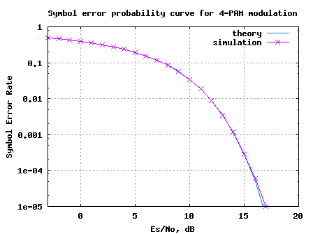
Figure: Symbol Error Rate for 4-PAM modulation
Reference
[DIG-COMM-BARRY-LEE-MESSERSCHMITT] Digital Communication: Third Edition, by John R. Barry, Edward A. Lee, David G. Messerschmitt
Hello Krishna,
I am pretty new to DSP but i will like a heads up on how to model chromatic dispersion in MATLAB and maybe how to simulate QPSK as well.Thank you.
@Ty: chromatic dispersion? – not studied that topic. 🙂
Hi Krishna i am facing a difficulty getten why included the SQRT of decimal SNR ad a variance of the output signal ? y = s + 10^(-Es_N0_dB(ii)/20)*n; i am trying to link this with analysis in Proakis 4th edition. y should be normally distributed with mean od TX signal and variance of noise.
i think i am missing something here
@Hamid: The noise is a voltage a signal. Hence the scaling of dB value by 1/20.
thanks a lot!!
Can you please explain me about the programs of 8 PAM and 16PAM?
please help me with this?
@varma: One can treat 16QAM as two independent 16PAM on the real and imaginary part.
https://dsplog.com/2007/12/09/symbol-error-rate-for-16-qam/
https://dsplog.com/2008/06/05/16qam-bit-error-gray-mapping/
Hi,
I went through the above bit error rate calculation for 4-PAM derivation. I have two questions:
1) why did you give the name of variable (E16PAM) that is used to calculate the average energy of the 4-PAM constellation?
2) in the above expression, it seems to me you are using energy Eb and Es are equal. But in case of 4-PAM two bits are mapped into 1 symbol, thus the energy of bit and symbol cannot be the same, right?
@dsp: Thanks much. Replies:
1) The name E_{16PAM} is a typo, though the value of 5 is the right one. Changed the variable to E_{4PAM}. Thanks for pointing this out.
2) Infact, the post did not try to get to the Bit Error Rate. It computes the symbol error rate (ser) vs symbol to noise ratio (Es/N0) plot. But you are right, Eb/N0 and Es/N0 is different for the 4PAM case…
Thank you for this hard work, but can you tell me what if instead of pulse amplitude modulation scheme we use a noise variance modulation scheme with variance [1,2,3,4]
Thank you
@Hamad: Sorry, I have not tried that.
hi
dear i m doing my dessertation bt i need simulation on link budget analysis through matlab i need command for that like RF tools ha rftool same like that i need command for link budget plz help me or send the link on my email thanks
inamkhan_swati@yahoo.com
regards
Inamullah from united kingdom 00447765001348
@inamullah: Sorry, am not aware. However, did you checkout some of the functions in RF toolbox or Communications toolbox in Matlab?
Hi,
Unfortunately, my mathematics got a little bit rusty. Could you help me with the step where you calculated p(e/s3)? I’m not sure how you got to the erfc() form –> First, the limits were “-inf” to “2*sqrt(Eb/5)”, than ” ” to “inf”. I tried to substitute as you did. –> z=y – sqrt(..) –> dz/dy=1 –> limits z=-inf -sqr() = -inf ….so its -inf , you ..you know. Additionally, how you got the N0 into the limits. Sorry, I really forgot how to do this. Orginally, I wanted to calculated the same as you did but with the Q() function.
Thanks,
Martin
@Martin: You can substitute z =(y – 3sqrt(Es/5))/sqrt(N0). With that substitution, the limits change from -Inf to 2sqrt(Es/5) to -Inf to -sqrt(Es/(5N0)). The latter is same integral from sqrt(Es/(5N0)) to Inf.
Agree?
Oh thank you. I forgot the sqrt(No). What a mistake.
Hi guys!
What happens if the messages are not equipropable???
I got a problem with defiining the thresholds.
i encoded my signal first with 5,2 block code and then converted to 4pam. I don’t know how to find the bit error rate or SER. can you please guide me?
@Richard: For finding the symbol error rate, compare the transmit and received constellation points. For computing BER, convert the received constellation into code bits, perform decoding and then compare the transmit and received bits. Good luck.
What is the formula for theoretical value? I would like to find coding gain.
I saw a formula at your page:
http://www.commsdesign.com/article/printableArticle.jhtml?articleID=208802825
The formula is near the end of the article. Should I use that?
Thanks in advance.
@Richard: I have not assumed any coding in this writeup. Maybe I did not understand your query.
could u please tell me the noise standard deviation for 8-PAM and the theoritical value of error probability of 8-PAM in AGWN channel?? thks before..
@N.A: Chapter 5.2.6 of Digital Communications by John Proakis, discuss the symbol error rate for a general M-PAM case. Plz check that out.
Can you advise me how I can stimulate the 8-PAM with a repeated input bit sequence of {101 000 100 101 100 100 100 011 001 100 110 110} , to produce the symbol error probability with less than 10^-4 ?
@cheri: You may start of with finding assign each bit groups to constellation points from [-7, -5, -3, -1, 1, 3 , 5, 7]/sqrt(21), and compute the bit error rate. For simplifying the simulations, try with zero noise and then later add noise. For high values of Eb/N0, you should be able to get BER less than 10^-4. Good luck.
Using MATLAB, perform a Monte Carlo simulation of the four-level (quaternary) PAM communication system that employs a signal correlator.
• N = 10,000 transmitted symbols at different values of the average bit SNR
• Consider average bit SNR in the range of 0 to 12 dB.
• For convenience, normalize the distance parameter d = 1 and vary σ0.
I need the MATLAB graph please… I cant download MATLAB on my pc.. please help me someone… my due is tomoro… please…
@Vini: Please refer to the post on symbol error rate for 4-PAM simulations:
https://dsplog.com/2007/10/07/symbol-error-rate-for-pam/
If you dont have Matlab, you may download Octave and use.
Nice way of using the find syntax …
I did the same simulation using nested for loops and it generates the same results, with a tradeoff of the script being slower. 🙁
@jsrt54: Glad to hear.
i am looking for best modulation technique suitable for software radio and which parameters affect it the most.please guide me..
@somnath: As I see, every modulation technique has its own pros and cons. For eg.
BPSK is simpler and requiers low SNR to work, but the data rate is less.
64QAM is relatively complex, but requires high SNR to work and we have good data rate.
So, in typical systems (like 802.11a wireless LANs), one finds different data rate specifications like 6, 9, 12, … 48, 54Mps. Based on the SNR constraints, the modem adapts to an optimal data rate maximizing the throughput.
These constraints should be similiar in software defined radio too.
Hope this helps.
@surbhi: I have not written a post on MSK demodulation, but have written on
(a) BER computation with FSK
https://dsplog.com/2007/08/30/bit-error-rate-for-frequency-shift-keying-with-coherent-demodulation/
(b) Generation of an MSK transmission
https://dsplog.com/2008/01/19/simulating-minimum-shift-keying-transmitter/
Hope these two posts help to achieve your goal of doing MSK with diversity. All the best.
hello sir,
good to see such a organised blog. its all your hard work.
sir, i m working on diversity along with MSK modulation. whenever we use matlab in built function for decoding it gives an error. please tell me how to find BER using MSK modulation
@Sravani: Yes, since each symbol carries two bits in 4-PAM,
Es/No = 2Eb/No
So for 4- PAM
Es/N0=2*Eb/N0
that is the only change we need to do??
@mohit: For BER, one would want to assign bits to constellation points (typically using Gray mapping). Then based on the received constellation point, map this to bits and count the errors.
Typically, if one assumes Gray mapping,
Pb = Ps/k.
Since each constellation carries k bits, then
Es/No = k*Eb/No.
You may refer to the posts @
https://dsplog.com/tag/gray/
for reference.
Hope this helps.
You have generated the symbol error probability.
What would be the difference if i wanted to do it for bit error probability?
Thanks
good
thankyou very much … the link you gave is helping me alot … you are great thanks alot once again
@johny: Dont worry and of-course do not be desperate. Start reading the articles slowly with a clam-clear mind. Things will fall in place. In the meanwhile, I happened to see a nice article from Mathworks
“Modeling a Communications System Using the Communications Toolbox” URI: http://www.mathworks.com/products/demos/commtlbx/commsys/commsdemo.html
It goes step-by-step over the blocks in a typical communication link. Nice read.
kindly tell me from where should i start programming the communication things in MATLAB i am facing alot of difficulties. Waiting desperately for your reply …
thnks in advance