Given that we have went over the symbol error probability for 4-PAM and symbol error rate for 4-QAM , let us extend the understanding to find the symbol error probability for 16-QAM (16 Quadrature Amplitude Modulation). Consider a typical 16-QAM modulation scheme where the alphabets (Refer example 5-37 in [DIG-COMM-BARRY-LEE-MESSERSCHMITT]).
are used.
The average energy of the 16-QAM constellation is (here). The 16-QAM constellation is as shown in the figure below
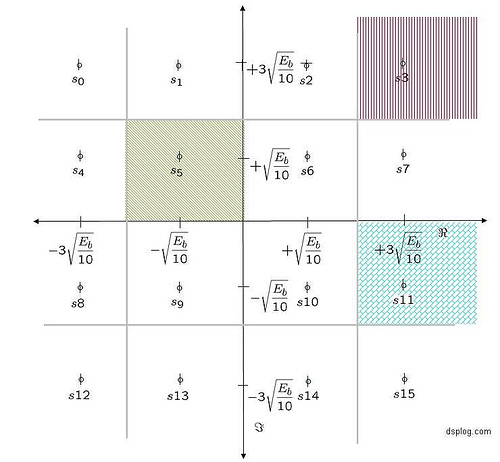
Figure: 16-QAM constellation
Noise model
Assuming that the additive noise follows the Gaussian probability distribution function,
with
and
.
Computing the probability of error
Consider the symbol in the inside, for example
The conditional probability distribution function (PDF) of given
was transmitted is:
.
As can be seen from the above figure, the symbol is decoded correctly only if
falls in the area in the black hashed region i.e.
.
Using the equations from (symbol error probability of 4-PAM as reference)
.
The probability of being decoded incorrectly is,
.
Consider the symbol in the corner, for example
The conditional probability distribution function (PDF) of given
was transmitted is:
.
As can be seen from the above figure, the symbol is decoded correctly only if
falls in the area in the red hashed region i.e.
.
Using the equations from (symbol error probability of 4-QAM as reference)
.
The probability of being decoded incorrectly is,
.
Consider the symbol which is not in the corner OR not in the inside, for example
The conditional probability distribution function (PDF) of given
was transmitted is:
.
As can be seen from the above figure, the symbol is decoded correctly only if
falls in the area in the blue hashed region i.e.
.
Using the above two cases are reference,
.
The probability of being decoded incorrectly is,
.
Total probability of symbol error
Assuming that all the symbols are equally likely (4 in the middle, 4 in the corner and the rest 8), the total probability of symbol error is,
.
Simulation model
Simple Matlab/Octave code for generating 16QAM constellation, transmission through AWGN channel and computing the simulated symbol error rate.
Click here to download : Matlab/Octave script for simulating 16QAM symbol error rate
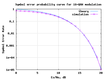
Figure: Symbol Error Rate curve for 16QAM modulation
Observations
1. Can observe that for low values, the theoretical results seem to be ‘pessimistic’ ‘optimistic’ compared to the simulated results. This is because for the approximated theoretical equation, the
term was ignored. However, this approximation is valid only when the
term is small, which need not be necessarily true for low
values.
Reference
[DIG-COMM-BARRY-LEE-MESSERSCHMITT] Digital Communication: Third Edition, by John R. Barry, Edward A. Lee, David G. Messerschmitt
Hope this helps.
Krishna
In The name of God
This is the best educational website for me.
Thank you so much.
Anoyher helpful link…..thank u very much….u rock
hi
could you please send me 4QAM bit error rate code?
Thank you
@NCH:
https://dsplog.com/2007/11/06/symbol-error-rate-for-4-qam/
hello
please explain for me modulation 16qam by matlab codes
thanks
@Vahid: This post does that. For bit error rate with Gray coded 16qam, please refer
https://dsplog.com/2008/06/05/16qam-bit-error-gray-mapping/
hi Krishna please i have a project on modelling simulation of OFDM on power line communication i need m-file
please help me
@ben: Sorry, I have not studied power line communication
hi… Im doing my project in 2D channel estimation for ofdm system. I have a doubt whether its possible to plot ( no of bits vs SNR plot) ., (SNR transitted vs SNR recieved).. please do help me
@hera: Yes, plotting should not be a problem
Hi Krishna,
Thank you for your answer 🙂
I have found it in your post
https://dsplog.com/db-install/wp-content/uploads/2008/04/script_m_qam_ser.m
but I don’t know how implement for M-ary?
Please could you help me
Thank you again your help.
regards,
@Hassan: Ah, good. In that code, by default, the simulation is for 64 QAM symol error rate
Hi,
I need the Matlab code example for simulation of BER vs SNR for M-ary 64QAM.
Could you help me?
regards,
Hassan
Hassan: I have a post on 16 QAM Bit Error Rate @ https://dsplog.com/2008/06/05/16qam-bit-error-gray-mapping
Hope that helps.
Hello krishna, thank you for your articles, they are very helpful. Forgive me for bad english. I would like to ask why there is a deviation between the 2 curves in 16QAM in your two articles. I dont undrestand this, could you please help ?
I mean the above curve and the curve in this article http://www.eetimes.com/design/signal-processing-dsp/4017668/Modulation-roundup-error-rates-noise-and-capacity?pageNumber=0
Thanks
@meps: What is the deviation which you are refering to? I was comparing Symbol Error Rate vs Es/N0 and both looked comparable.
hi, i want to ask about 16 QAM matlab code under this web. why the mapping is a symbol for each bit? for N=256, your mapping result 256 symbol.
i read in some reference, 16 QAM has 1 symbol for every 4 bit. it means for N=256, will craete 64 symbol.
can you explain it? thanks
@adi: For 16 QAM, each symbol carries 4 bit. The simulation code is computing Symbol error rate and not bit error rate.
How many phases and Amplitude does a 16-QAM have?
@ASG: That one should be simple. Did you figure out the answer? 🙂
hi,
i need a code for 64 QAM modulation, also the BER and FER for this modulation, where the input is a sequence of ‘0’ and ‘1’.
thank you
@abi: The matlab code in this post (for 16-QAM case) can be easily modified for the 64-QAM case.
Wonderful Jobs.
hi, plz could you send me 16QAM Bit Error Rate simulatio?
@shadat: please refer to the post
https://dsplog.com/2008/06/05/16qam-bit-error-gray-mapping/
may i know the error probability (Pb) of 32-QAM..?? thks…
@N.A: Please refer the posts
https://dsplog.com/2008/05/24/article-in-dspdesignlinecom-m-qam-symbol-error/
http://www.embedded.com/columns/technicalinsights/207801597?_requestid=88879
hi!
I have simulated 4-QAM, 16QAM under AWGN and 4QAM under rayleigh fading and got good results. but when I simulate the 16QAM under rayleigh fading the decoder (MLD) hardly decodes even up to 50dB (BER=0.08102). Can anyone tell me what I’m doing wrong? because I’m only adding coefficient (y = h*x+n)
Thanks
@Jules: Maybe your 16QAM demodulation is the culprit? You can have a look at 16QAM demodulator code @
https://dsplog.com/2007/12/09/symbol-error-rate-for-16-qam/
https://dsplog.com/2008/06/05/16qam-bit-error-gray-mapping/
Good luck.
thank you Krishna
hi…….
i am doing project in mimo signal detection using combined qrd-m and dfe detection technique for simple and efficient detection Can u please help me out with it ,thank u.
@balu: You can email me your queries (but, sorry i cant do code debug). Good luck in your algorithm explorations.
Hi!
I am doing a project on digital hardware implementation of D64-QAM for voice band data transmission. Can u please help me out with it .
@Altaf: Though I have not worked on the above mentioned technology, you can mail me with your queries. I will try answer to the best of my knowledge.
You have given the matlab code for simulating the SER of 16 QAM in AWGN channel. Can you provide some hints towards SER of 16 QAM in Rayleigh fading channel with diversity combining, i.e. how to incorporate the changes in your Matlab code given for AWGN case.
@soumendra: Broadly I can suggest:
a) First introduce only Rayleigh channel, have an equalizer as discussed in the post https://dsplog.com/2008/08/10/ber-bpsk-rayleigh-channel/ and obtain the reference curves
b) Once a) is done, introduce multiple receive chains and using the post https://dsplog.com/2008/09/28/maximal-ratio-combining/ as a reference, obtain the curves
Good luck.
Thanks very much Krishna for your guidelines. I have still another query.
Regarding dual-hop Rayleigh channel (means between Tx and Rx, there exists another transceiver node), Can you provide some hints what would be the Equalization term if h1 and h2 are channel parameters in dual-hop case.
@soumendra: Well, I would think that for each hop, you might be doing an equalization. Agree?
No, Sir. I am doing the equalization after two-hop by dividing the received signal by (h1.*h2). Which one is correct? after each hop or after two-hops.
@soumendra: Well, I believe the idea behind using relay communication is to improve the reliability of the link. So, the intermediete node might be doing something. Couple of ways are:
a) decode the data, and then re-transmit.
b) amplify the signal + noise, and then re-transmit.
c) more ?
Depending on your system design, you may chose the appropriate approach.
Yes, Sir…. I have adopted the strategy (b) amplify the signal + noise, and then re-transmit….So, the equalization term after two-hop would be dividing the received signal by (G*h1.*h2) where G is the amplification factor. Am I right?
@soumendra: Yes, it sounds correct.
y1 = h1x + n1
y2 = h2*g*y1+n2 = h2*g*(h1x+n1) + n2 = h2gh1x + h2n1 + n2
Other way could be doing equalization after each hop, i.e.
y1 = h1x + n1; y1=y1/h1;
y2 = h2*g*y1+n2 = h2*g*(x+(n1/h1)) + n2 = h2*g*x + g*(h2/h1)*n1 + n2;
y2=y2/(g*h2);
Which one would be appropriate ? doing equalization after each hop or after two-hop.
@soumendra: I have a feeling that your proposal i.e. doing equalization at each hop might be better. However, one needs to do the math to confirm. Please try simulating it and let us know.
As an added thought, a third approach will be to decode x at y1 (after equalization) and then re-transmit.
hi
i wish i find any help in the topic of using ofdm in power line communication
if any one get any results by using matlab codes i wish i can have these results
thanks
Hi,
Sorry for this new comment but just to be clear, I mean on figure with SER curves
Hi,
I think that on figure is an error(horizontal axes)
It is not realy Es/No but Eb/No .
(see MATLAB bertool for example)
Am I right?
Best regards
@Melinda: No, its indeed Es/N0. Was wondering, what made you think otherwise.
Hi,
Why points on picture above are as Eb ?
On https://dsplog.com/2007/11/06/symbol-error-rate-for-4-qam/ – QPSK case is as Es?
Can You please explain this.
Best regards
@Melinda: Hmm… yes. I just checked. All the equations and BER plots are using Es/N0. However, I missed correcting the constellation plot diagram. Yes, the constellation point diagram should have shown Es/N0 (instead of Eb/N0).
Thanks for noticing and pointing that out. I will correct in future.
@Philips: I do not know much about the channel model for power line communications (except that the channel is a wire, ofcourse). 🙂
However, for OFDM aspect may I point to couple of articles which I have written in the past.
(a) Understanding an OFDM transmission
URI: https://dsplog.com/2008/02/03/understanding-an-ofdm-transmission/
(b) Cylcic prefix in Orthogonal Frequency Division Multiplexing
URI: https://dsplog.com/2008/02/17/cylcic-prefix-in-orthogonal-frequency-division-multiplexing/
(c) Peak to Average Power Ratio for OFDM
URI: https://dsplog.com/2008/02/24/peak-to-average-power-ratio-for-ofdm/
Hi friends,
I’m studying a project which is a simulated OFDM on PLC(PowerLine Communication) with M-files in MatLab. I have not imaged my work yet. But I’ve read some documents which is described about OFDM and PLC(PowerLine Communication) models. Could you help me! Thank you so much.
me too 🙁
anybody help us
thanks
@Tesla: I do not know much about the channel model for power line communications (except that the channel is a wire, ofcourse). 🙂
However, for OFDM aspect may I point to couple of articles which I have written in the past.
(a) Understanding an OFDM transmission
URI: https://dsplog.com/2008/02/03/understanding-an-ofdm-transmission/
(b) Cylcic prefix in Orthogonal Frequency Division Multiplexing
URI: https://dsplog.com/2008/02/17/cylcic-prefix-in-orthogonal-frequency-division-multiplexing/
(c) Peak to Average Power Ratio for OFDM
URI: https://dsplog.com/2008/02/24/peak-to-average-power-ratio-for-ofdm/
@hwan:
As you maybe aware, depending on the order of the modulation, constellation symbol might carry k bits, where k=log2(M). Typically k=1 for BPSK, 2 for QPSK, 4 for 16QAM etc.
The term SNR/bit refers to the energy required for transmitting a bit. So if the signal (constellation symbol) to noise ratio is Es/No, as each constellation carries k bits, then Es/No = k*Eb/No
Then term SNR/bit is equal to Eb/No.
Hope this helps.
what is difference between Eb/No to SNR/bit.
many communication book show us case of SNR/bit.
i.e)John G.proakis ‘communication systems engineering’
@rajesh: Well, for square QAM, you need to arrange them into {+/-1+/-j, +/-3,+/-3j,+/-3,+/-1j,+/-1,+/-3j} constellation points.
hi,
if i have 16 distinct points, what are the conditions on them to form 16 qam ???
@mdkn45: Typically, we can assume that the bits assigned to constellation points are grey coded (i.e. bit groups allocated to adjacent symbols differ by only one bit). Which means that each symbol error causes only 1 out of 4 bits to be incorrectly detected. Given so, the bit error probability is 1/4th the symbol error probability.
Additionally, since we are transmitting 4 bits in a symbol,
the each symbol carries energy of four bits i.e Es/No = 4*Eb/No.
Combining, the bit error probability comes to
BER_{16QAM} = (3/8)*erfc(sqrt(4Eb/10No)).
Agree?
hi, it’s very useful. But i want to bit error. What can i do?