In TETRA specifications, one of the modulation technique used is Differential Quaternary Phase Shift Keying (DQPSK). We will discuss the bit error rate with non-coherent demodulation of
DQPSK in Additive White Gaussian Noise (AWGN) channel.
pi/4 DQPSK
The incoming bit sequence is grouped into two bits and is mapped into differential phase as follows:
| B(2k-1) | B(2k) | |
| 1 | 1 | |
| 0 | 1 | |
| 0 | 0 | |
| 1 | 0 |
Table : Phase transitions for DQPSK modulation (Ref Table 5.1 of ETSI 301-893 V3.2.1)
The modulation symbol is formed by applying a phase offset to previous symbol
and is defined as follows:
and
.
Alternately, the phase transitions can be represented as
.
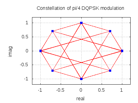
The constellation of the DQPSK occupies phase values separated by
as shown below in the blue dots. The red lines shows all possible phase transitions.
Figure: Constellation of DQPSK (Ref Figure 5.1 of ETSI 301-893 V3.2.1)
Channel Model
The transmitted waveform gets corrupted by noise , typically referred to as Additive White Gaussian Noise (AWGN).
Additive : As the noise gets ‘added’ (and not multiplied) to the received signal
White : The spectrum of the noise if flat for all frequencies.
Gaussian : The values of the noise follows the Gaussian probability distribution function,
with mean and
variance .
The received symbol is,
Non Coherent Receiver
A non-coherent receiver relies on the phase transitions between consecutive symbols to form an estimate of the transmitted bits. The sequence of operation is as follows:
a) On the received symbols estimate the phase
b) Find the delta of the estimated phase between consecutive symbols
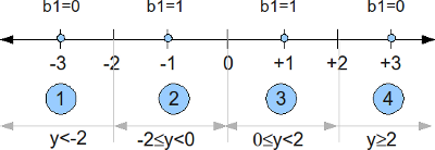
c) Quantize the estimated delta phase values lying from as follows and convert to bits per the following encoding:
.
Figure: Received delta phase to bit mapping
The theoretical bit error rate defined with the mapping above is (Ref Chapter 5.2.8 of Digital Communications by Proakis, 4th Edition)
,
where
,
,
and
is the modified Bessel function of first kind.
Simulation results
The script performs the following
(a) Generate random binary sequence of +1’s and 0’s.
(b) Group two bits together and apply DQPSK modulation
(c) Add white Gaussian noise.
(d) At the receiver, estimate the phase of the received symbols. Based on the delta of the received phase, estimate the transmitted bits
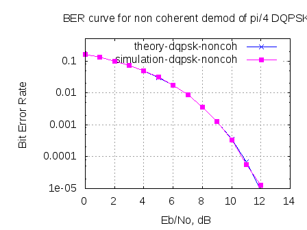
(e) Repeat for multiple values of and plot the simulation and theoretical results.
Click here to download the script for simulating BER of pi/4 DQPSK with non-coherent demodulation at the receiver
Figure: BER plot for DQPSK with non-coherent demodulation
Observations
Can see good agreement between simulated and theoretical results. 🙂

Hi, what is the different between pi/4 DQPSK and DQPSK ? How can i change the code to make it work for DQPSK ? Thanks
@bai: have discussed coherent demodulation of DBPSK in an earlier post.
https://dsplog.com/2007/09/30/coherent-demodulation-of-dbpsk/
Hi, may I know how is it different from DQPSK, how can I change the code to get the BER for DQPSK ? Please advise.
@Bai: I think a typical DQPSK will occupy only four constellation points, where as this scheme is using 8 constellation points. I think this is done to minimize the phase transitions
http://en.wikipedia.org/wiki/Phase-shift_keying#.CF.80_.2F4.E2.80.93QPSK
Thank you very much for this article. It’s very nice
Dule Markovic, Belgrade, Serbia
Hi Krishna,
Your blog helps me a lot!
Thanks a lot!
Now I’m still cofused by the modulation and demodualtion about D8PSK, do you have some articles and matlab codes about it?
Hoping for your help!
Thanks!
@Ivy: Well, I have not discussed D8PSK till date. Quite likely in the near future.
Hi Krishna,
Thanks for sharing some concepts on pi/4 DQPSK. The article was really helpful. I would like to know if you would be doing any codes or if you can share some concepts on star QAM and PSAM (Pilot Symbol Assisted modulation).
@Ankur: Can you please point me to literature describing star QAM and PSAM