In this post, let us derive the theoretical bit error probability for 16PSK modulation using Gray coded mapping. For deriving the equation, we will refer material from the following posts:
(a) Symbol Error Rate for 16PSK
(b) Gray code to Binary code conversion for PSK
(c) Binary to Gray code conversion for PSK
As discussed in the previous posts, the key feature of Gray code is that adjacent symbols differ by only one bit. The 16PSK constellation with Gray mapping can be as shown in the figure below.
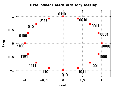
Figure: 16PSK constellation plot with Gray coded bit-mapping
From the discussion on symbol error rate for 16PSK in AWGN, we have proved that the symbol error rate for an M-PSK modulation is,
.
Relation between bit energy Eb/No to symbol energy Es/No
As can be seen from the constellation plot, for a 16PSK modulation, each symbol transmits bits. In general, for an M-PSK modulation the number bits in each constellation symbol is,
.
Since each symbol consists of bits, the symbol to noise ratio
is
times the bit to noise ratio
, ie.
.
Relation between symbol error and bit error
For reasonable symbol to noise ratio , the symbol will be in error when noise causes the symbol to fall in the adjacent symbol bin. Now thanks to the Gray coded mapping, even if the symbol goes into the adjacent symbol there will be only 1 bit in error from the
bits. So, the relation between symbol error and bit error is,
.
Note:
For very low symbol to noise ratio, the noise can cause the symbol to fall into the non-adjacent symbol bin. This may cause more than 1 bit error for each symbol error. However, we can ignore this case considering that we are interested only in reasonably high values of symbol to noise ratio. 🙂
Probability of bit error for M-PSK modulation
Combining the above two equations, the bit error probability for a general M-PSK modulation is,
.
Matlab/Octave script for simulation 16-PSK BER
The Matlab/Octave script performs the following:
(a) Generation of random 1’s and 0’s
(b) Assigning group of 4 bits to each constellation symbol per the Gray mapping
(c) Addition of white Gaussian Noise
(d) Demodulation of PSK symbols and
(e) De-mapping per decimal to Gray conversion
(f) Counting the number of bit errors
(g) Running this for each value of Eb/No in steps of 1dB.
Click here to download: Matlab/Octave script for simulating 16PSK bit error rate
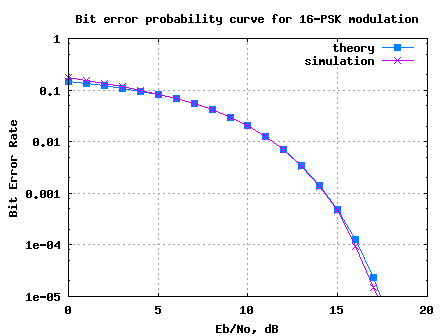
Figure: Bit error rate plot for 16PSK modulation using Gray mapping
Observations
1. The simulated results show good agreement with the theoretical results.
2. For low Eb/No values, we can see that the simulated bit error rate is slightly higher than that expected by theory. As explained above, this can be attributed to noise causing symbol to fall into the non-adjacent bin.
Hope this helps, Krishna
sir please explain Gray coded constellation mapping part in this script
@khushi: Please check
https://dsplog.com/2008/05/12/gray-code-to-binary-conversion-for-psk-pam/
https://dsplog.com/2008/05/11/binary-to-gray-code-conversion-psk-pam/
dear sir,
i want
theoryBer_16QAM
@norseen: Please take a look at
16QAM Bit Error Rate (BER) with Gray mapping
https://dsplog.com/2008/06/05/16qam-bit-error-gray-mapping/
@norseen: Please take a look at
16QAM Bit Error Rate with Gray mapping
https://dsplog.com/2008/06/05/16qam-bit-error-gray-mapping/
Yes it is throwing an error.
And also in the http://images.dsplog.com/db-install/wp-content/uploads/2008/06/script_16qam_gray_mapping_bit_error_rate.m
just changing M=16 to 8 does not work..How can i do the same code for 8QAM??? pls help
@Mohammed: The script is throwing an error?
Hello Sir! i would really appreciate if for the 16QAM bit error rate instead of adding Gaussian noise other types of noise eg: impulsive is added.How can i do that?Pls help
@Mohammed: You can change the noise model from AWGN.
hello sir!!!!!!!!!!
plz. sir help me in finding 32 psk matlab code.
@shweta: The script used in this post can be easily extended to 32PSK case (by changing to M=32)
thank u sir.sir if we increase the BER. The signal to noise ratio will decrease or not? plz reply…..
@shweta: It’s the other way – a lower signal to noise ratio will cause higher bit error rate.
hi man how are u ?
i just want to ask that for 8-PSK is the same for 16-PSK and the only difference is change M from 16 to 8 ???
i look forward to hear from you
regards
Deep
@Deep: Yes, changing 16 to 8 should suffice.
hello:
i’d like to order anything about “The decorrelating detector”
thnx.
@omer: Are you referring to decorrelating detector used in spread spectrum cases? Sorry, I do not have articles on that.
dear krishna….
iam working on ofdm system with rayleigh channel multipath using jakes model and the syntax that is availanle in matlab ‘chan=rayleighchan(ts,fd,tau,gaindb)’ but i face aproblem that when i send the data bits through this channel with three paths i always get bit error rate equal to 0.5 or little less so iam asking you if could help me to exceed this problem pls…send me the answer if you could on email…
thanks…
@maytham: Are you equalizing for the effect of the channel in receiver?
Hi,
I have a question on the part “Relation between symbol error and bit error”. I have read in many books and know for a fact that Pb = Ps / k, but I have not heard a reasonable explanation for that fact. Could you elaborate?
Sir,
When 16PSK is to convert into passband, how can I recover the phase in the demodulator stage? Do you know some method or equation in order to simulate it?
Thanks again, sir.
Sir,
Is it possible that the modulated signal from this simulation can be viewed in time domain? As if your looking it in the oscilloscope.
Thank you sir
dear sir,
i want
1.matalb script for simulating BER for QPSK modulation in AWGN chnanel.
2.matlab script for simulating BER for 16QAM modulation in AWGN chnanel.
3.Matlab script for simulating BER for 64QAM modulation in AWGN chnanel.
could u help me please i will very greatful to you.
@rashed: Please have a look at
a) https://dsplog.com/2007/11/06/symbol-error-rate-for-4-qam/
b) https://dsplog.com/2008/06/05/16qam-bit-error-gray-mapping/
c) https://dsplog.com/2008/07/08/compare-bpsk-qpsk-4pam-16qam-16psk-64qam-32psk/
good luck
Hi sir,
i want matlab script for comparing bit error probabilities of the 16 QAM and 16 PSK schemes using OFDM.
could u please help.
i will be very thankful to u.
please reply as soon as possible
@Ruby: Hope the post helps
https://dsplog.com/2008/03/29/comparing-16psk-vs-16qam-for-symbol-error-rate/
You can easily adapt to the OFDM case.
Hi sir,
i want matlab script for comparing bit error probabilities of the 16 QAM and 16 PSK schemes using OFDM.
could u please help.
@Ruby: Hope this post helps.
https://dsplog.com/2008/03/29/comparing-16psk-vs-16qam-for-symbol-error-rate/
i need the matlab code of coherent detection multiple phase shift keying
@shafqat abbas: Hope the post on symbol error rate with 16psk helps
https://dsplog.com/2008/03/18/symbol-error-rate-for-16psk/
hi..ı need QPSK modulatıon with gray mapping technique as a matlab code immediatelly.if you have please post ıt.thank u
@gokalp: Sorry, I do not have posts on BER for QPSK with Gray mapping. But, it should be reasonably straightforward to scale down 16QAM BER with Gray mapping to the 4QAM case
https://dsplog.com/2008/06/05/16qam-bit-error-gray-mapping/
Good luck.
Hi,
i wana matlab script for comparing bit error probabilities of the 64 QAM and 64 PSK schemes, plz?
@BusyWasp: Please check the posts
https://dsplog.com/2008/07/08/compare-bpsk-qpsk-4pam-16qam-16psk-64qam-32psk/
http://www.dspdesignline.com/howto/208801783;jsessionid=KQBZX4ZJRFCX0QSNDLRSKHSCJUNN2JVN?pgno=1
I have discussed the M-QAM case, which you can adapt to 64-QAM.
The post and code in 16-PSK is also discussing M-PSK case.
https://dsplog.com/2008/03/18/symbol-error-rate-for-16psk/
Good luck.
sir i need matlab script for hamming code (Bit error rate plot for hamming code)
@Iqtadar: Please check
https://dsplog.com/2009/09/29/hamming-74-code-with-hard-decision-decoding/
hello,
sorry i find that.
hello,
where is matlab script for psk-16 with gray code? I found here only psk-16 without gray code. but i need that. can u post that?
@sumit: Hmm.. 🙂 Why do you say that this post discuss about BER for 16PSK without gray code?