In the past, we had discussed two transmit, one receive antenna Alamouti Space Time Block Coding (STBC) scheme. In this post, lets us discuss the impact of having two antennas at the receiver. For the discussion, we will assume that the channel is a flat fading Rayleigh multipath channel and the modulation is BPSK.
Alamouti STBC with two receive antenna
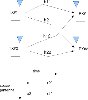
The principle of space time block coding with 2 transmit antenna and one receive antenna is explained in the post on Alamouti STBC. With two receive antenna’s the system can be modeled as shown in the figure below.
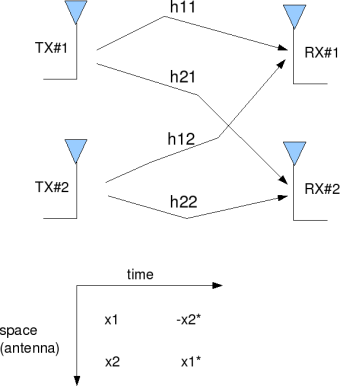
Figure: 2 Transmit 2 Receive Alamouti STBC
For discussion on the channel and noise model, please refer to the post on two transmit, one receive antenna Alamouti Space Time Block Coding (STBC) scheme.
The received signal in the first time slot is,
.
Assuming that the channel remains constant for the second time slot, the received signal is in the second time slot is,
where
are the received information at time slot 1 on receive antenna 1, 2 respectively,
are the received information at time slot 2 on receive antenna 1, 2 respectively,
is the channel from
receive antenna to
transmit antenna,
,
are the transmitted symbols,
are the noise at time slot 1 on receive antenna 1, 2 respectively and
are the noise at time slot 2 on receive antenna 1, 2 respectively.
Combining the equations at time slot 1 and 2,
.
Let us define .
To solve for , we know that we need to find the inverse of
.
We know, for a general m x n matrix, the pseudo inverse is defined as,
.
The term,
Since this is a diagonal matrix, the inverse is just the inverse of the diagonal elements, i.e
The estimate of the transmitted symbol is,
.
Simulation Model
The Matlab/Octave script performs the following
(a) Generate random binary sequence of +1’s and -1’s.
(b) Group them into pair of two symbols
(c) Code it per the Alamouti Space Time code, multiply the symbols with the channel and then add white Gaussian noise.
(d) Equalize the received symbols
(e) Perform hard decision decoding and count the bit errors
(f) Repeat for multiple values of and plot the simulation and theoretical results.
Click here to download Matlab/Octave script for computing BER for 2 transmit 2 receive Alamouti STBC for BPSK modulation in flat fading Rayleigh channel
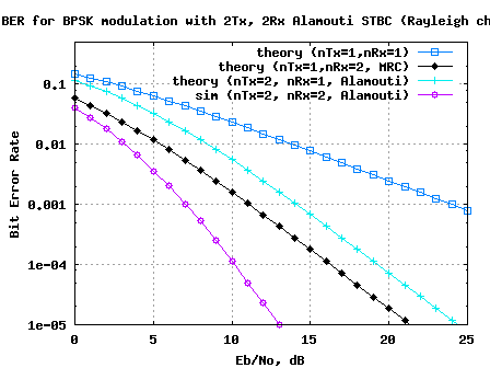
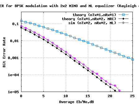
Figure: BER plot for 2 transmi 2 receive Alamouti STBC
Observations
1. Can observe that the BER performance is much better than 1 transmit 2 receive MRC case. This is because the effective channel concatenating the information from 2 receive antennas over two symbols results in a diversity order of 4.
2. In general, with receive antennas, the diversity order for 2 transmit antenna Alamouti STBC is
.
3. As with the case of 2 transmit, 1 receive Alamouti STBC, the fact that is a diagonal matrix ensured that there is no cross talk between
,
after the equalizer and the noise term is still white.
Reference
[DIG-COMM-BARRY-LEE-MESSERSCHMITT] Digital Communication: Third Edition, by John R. Barry, Edward A. Lee, David G. Messerschmitt
A Simple Transmit Diversity Technique for Wireless Communication Siavash M Alamouti, IEEE Journal on selected areas in Communication, Vol 16, No, 8, October 1998
hj
What kind of simulation methods?
monte carlo methods, my guess
What kind of simulation methods?
@Dean88: monte carlo simulations
can you any one provide me algorithm or matlab code for spatial modulation.
@krishna: are you looking for posts on multiple antenna transmission/reception? if so, please checkout
https://dsplog.com/category/mimo/
Hi Krishna,
Do you know how to simulate 4×4 16QAM Symbol Error Rate under rayleigh condition? Please advise.
Regards,
@Jeremiah: For posts on MIMO and BPSK, please check out
https://dsplog.com/category/mimo/
how can we implement ALamouti Coding (2×1) or (2×2) in mobile WiMAX under different speeds of the subscarriers…?
@chiran: Are you referring to loading independent modulation schemes in different subcarriers. Yes, that is possible.
Dear Krishna sir,
I want to simulate 2×2 mimo ofdm system. But I am confused whether to perform channel coding(mimo) first or OFDM modulation first,. also where to insert the pilot for channel estimation? after MIMO or after OFDM modulation? Please reply
@kiran:
a) Typically, it is first the MIMO modulation, then OFDM. The model is
y = Hx + n
where
y is 2×1 matrix of received symbol
H is the 2×2 mimo channel
x is the 2×1 matrix of the transmited symbol
n is the 2×1 matrix of noise
b) Pilots need not be MIMO coded, and typically it is not. The pilots are defined in the subcarrier domain.
Helo sir plz help with Alamouti STBC with OFDM in presence of carrier frequncy offset with 16QAM and 64 QAM modulation. I have results for QPSK modulation but when I make changes accoring to QAM modulation I do not get desired results…PLZ…PLZ help me to solve this problem.
Thank u
@ankita: For posts on general M-QAM modulation with OFDM, please check out
https://dsplog.com/2012/01/01/symbol-error-rate-16qam-64qam-256qam/
For carrier frequency offset, please check
https://dsplog.com/2009/08/08/effect-of-ici-in-ofdm/
https://dsplog.com/2008/03/03/frequency-offset-estimation-using-80211a-short-preamble/
can you please help me with the equalisation part of STC Matrix B for 2×2 antennas..
|r0| =|h00 h01| |s0|
|r1| |h10 h11| |s1|
is the received signal.. We multiply with H-1 to get s0 and s1 back..
we get |h00|2 + |h01|2 + |h10|2 + |h11|2 for matrix A,
what will we get for matrix B??
@Vishwas: Are you looking for H^H, that is the Hermitian i.e. conjugate transpose of the matrix
Yes, I want the equations for Matrix B.. And also, can you please help me with HARQ. Any links or material regarding it will be very helpful.. I want to know about both types, Chase combining and incremental redundancy..
@Vishwas: Sorry, I have not written anything on HARQ
Helo sir,
I m working on STBC OFDM. I have used QPSK as my modulation technique. but whenever I change my modulation technique from QPSK to16 QAM or 64 QAM i do not get the desired results. Please help me with this
@ankita: For posts on general M-QAM modulation with OFDM, please check out
https://dsplog.com/2012/01/01/symbol-error-rate-16qam-64qam-256qam/
Dear sir,
This is my first time on your blog…
I am studying in UM(Malaysia), Working on a project on MIMO-OFDMA
I already have studied (I think) 9 hours at a stance, What you have created is a blessings for the new researchers,
My question is about the receiving section,
Can you tell me how the Parallel data is being handled at the Rx?
For an Example;
If I tried with a 2×2 antenna, (SIBC OFDMA), After getting the signal into the receiver,(Being equalized) how i am gonna recover my original data? can you explain or give me any ref??
Thanking you,
Tanbir
@Tanbir: One will have a buffer to convert the parallel data to serial and use. Check out the OFDM related posts @ OFDM https://dsplog.com/category/ofdm/
Dear Mr. Krishna,
If we use a simple AWGN channel model, instead of considering it to be Rayleigh fading then does that mean that the channel coefficients h1 and h2 equal 1? Since we are only adding noise? I dont know if I am asking a stupid question but it would nice if you could let me know.
Best,
Raj
@Rajopadhhay: Yes, assuming h1=h2=1 will take the Rayleigh fading out of the way 🙂
Sir,
I have been working on paper “improved interference cancellation scheme for two-user detection of alamouti code” and I derived all the required mathematical equations and proved for 2*2, 2*3, 2*m but i could’nt do the simulation please help me if you can…
@Jyothi: I wont be able to help in the coding part. Some quick pointers to help in debugging the code will be:
a) Make sure that the decoding has zero errors in no-noise case
b) Use BPSK modulation
Hello sir,
can you please explain cahnnel estimation in OFDM with providing matlab code..?
@urvik: The channel estimation in typical ofdm systems is relatively simple and is done with the aid of a known preamble.
The system model for each subcarrier is,
Y = HX + N, where
Y – is the received symbol
H – is the unknown channel
X – is the known preamble and
N – is the noise
The noisy estimate of channel H’ = Y/X
hello sir,
I am right now developing alamouti 4×4 scheme. So, i want to develope the combiner output for that. So, i need help that, whether i have to develope the combiner output equations for 4×4 as same manner or as different way. I need one more help about the internal discription about combiner circuit and channel estimator in alamouti.
@maharshi: what is the coding scheme for the 4×4 channel which you are using?
sir, i am doing for alamouti STBC. So, i am following same theory of 2×2, which is extended upto 4×4. And transmitting matrix is (s1 s2 s3 s4 ; s2 -s1* s4 -s3*; and two other rows). But now i am not able to produce the output of the combiner.
@maharshi: For debugging, try to build the decoder with no noise.
ok, so i need to take y=H*x.or i am not able
to get what u want to say???
@maharshi: the estimate h’ = (y+n)/x ~= y/x is a noisy estimate of h
can u plz help me out wid Alamouti OFDM with 16QAM and 64QAM modulation……
@Aditi: I do not have codes explicit for 16/64QAM modulation. But you can refer to some 16QAM/64QAM related posts @
https://dsplog.com/2012/01/01/symbol-error-rate-16qam-64qam-256qam/
https://dsplog.com/2008/07/08/compare-bpsk-qpsk-4pam-16qam-16psk-64qam-32psk/
https://dsplog.com/2008/06/05/16qam-bit-error-gray-mapping/
@Mr.Krishna Sankar: I modified my codes and combined to 16QAM concept (yours also), but the SER is not right. Which part that I need to concern about if I want to obtain a proper result? Thank you.
@ari: Make sure that the noise addition is correct. And the also the symbol to bit decoding.
Thank you for your reply sir,……
sir you are right the concepts of MIMO decoding is not getting affected by OFDM……………..But the problem with channel model in your code you take a channel with N coefficient but in practical case we have a channel of 3,5 or 10 tap, if channel have N coefficient so its becomes a frequency selective channel …so the channel model is very within in one ofdm symbol……(Plz help me sir)
@ashu: Well, even if the channel has multiple taps, as long as the tap duration is lesser than the cyclic prefix, the channel coefficient for each subcarrier can be treated as an independent flat fading. Have discussed this for a SISO rayleigh channel + OFDM case @
https://dsplog.com/2008/08/26/ofdm-rayleigh-channel-ber-bpsk/
First of all I would like to say thanks for such wonderful blog….sir presently i am working on MISO OFDM system,,sir in your blog you discuss about ofdm and mimo separately but not combined can you do so….
@ashu: Thanks.
The underlying concepts of MIMO decoding is not getting affected by OFDM. For OFDM related posts, please check out
https://dsplog.com/category/ofdm/
hello sir,
can u plz help out regarding the theoritical calculaton(BER) simulation for Almouti STBC with CFO…
thnx
@Aditi: Sorry, have not looked into that aspect
Sir can we make this Alamouti STBC coding for receiver antenna selection for MIMO OFDM?
& Can u please tell me what are these -x2* & x1*?
@MINAL: For OFDM related posts, please checkout https://dsplog.com/category/ofdm
Did you want to do receiver selection along with Alamouti STBC?
i want information about sfbc mapping and demapping. any one pls help me.
Hi sir,
First of all I would like to say thanks. bcz your coding 2×1 is more helpful for me.
Thank you sir,……
sir i need one help.. i need coding for 4×1, 3×1… i tried many time by change the coding, but i still getting error… so plz help me sir
@priya: Thanks. what is the code which you are using for 4×1, 3×1 cases? Can you please point me to that.
Further, are you getting zero error in the no noise case?
can you explain me about 4×4 mimo
thanx
@benza: I have not gone through the 4×4 mimo case, but you can find posts on the 2×2 MIMO with different equalizer structures in
https://dsplog.com/tag/mimo/
Hope this helps.
hi
plz help me for MATLAB. can u?
@mina: Hmm… you can post your query. will try to help.
I need matlab code help for STBC-OFDM and SFBC-OFDM urgently… sir please help me…
thanks
@Reetu: I do not have posts discussing OFDM and STBC combined, but have
http://www.dsplog.com/tag/ofdm
http://www.dsplog.com/tag/stbc
Hope the above can help you
Dear Krishna,
If i suppose there is feedback channel so reciever tells the transmitter the channel estimation,, then transmitter would do forward error correction ,this could be implemented if i multuplied modulated bits by 1/rayleigh fading. but when i did that, i didn`t get the plot. any suggestions about the reason?
@LEETHENG: Hmm… are you getting zero ber even in the case of no noise?
Also, try looking at https://dsplog.com/2009/04/13/transmit-beamforming/
Hello sir,
In Virtual MIMO I read that one mobile shares the transmitter in other mobiles so that it looks as if it has many antennas. But the thing is how will the neighboring mobile know of my data? For eg: if x1 and x2 are my data and in the first time slot I send x1 in my mobile transmitter and x2 in my neighboring mobile transmitter how will my neighbor have that data x2?
Thanks in advance.
@Venkataraman: Hmm… I have not read about the concept of virtual MIMO. Sorry
Hi Krishna
i want to implement Alamouti scheme with 2 transmit and one receive antenna using following equation for SINR = h112 +h122E (x12)/Sn2+h1k2.E(Xi2).
please help me.
@Jayashree: Please refer to
https://dsplog.com/2008/10/16/alamouti-stbc/
I want the transmission matrix for 2-transmit & 2-recieve antennas. Is there any mathematical procedure to get it?
@Amin: Did you want to check posts in https://dsplog.com/tag/mimo?
Hello Sir
Thanks for this info, it has really been helpful.
its simulation is in matlab can it be done matlab simulink or it is done in this blog
plz let me know sir.
@WASEEM: The code in the blog is in Matlab. Ofcourse, it can be done in Simulink (I do not not have simulink).
ok
Hello Sir,
I will write a program for 2×2 spatial Multiplexing and space time coding with 4-qam 16-qam modulation respective. But do not know to start it. I would like you suggest.
@Pattaraporn: Try to see if the code present in the following links help
https://dsplog.com/tag/mimo/
https://dsplog.com/tag/alamouti/
Hello Sir,
Thanks for this forum, it has really been helpful.
Please I would like to clarify something.
When you say
The estimate of the detected symbol is,
(x1,x2*) i was thinking why x2*, why not just (x1 and x2)
@Anchin: The x2* conjugate came up because it mode it more convenient to represent it in matrix notations.
hello sir,
why taps are used for OFDM in rayleigh channel with BPSK modulation? Is STBC with OFDM is same as STBC with MCCDMA
@dolly: My replies
a) It depends on the scenario which one wishes to simulate. I wanted to simulate a multipath channel case
b) Thats a difficult question to answer. Ofcourse the simplest answer is no, however there can be finer shades of gray depending on what you are trying to achieve with these two technologies.
I have a problem regarding a data transmission using SFBC-OFDM.
How this will be performed.
Hi Krishna, here is my question.
How did you combine the received signals?
Have you used MRC at the receiver?
I have a system of 2×2 with OFDM-STBC but i can’t understand how to sum up all the signals at the receiver side. After applying FFT at the receiver should i apply alamouti STBC and then MRC?
Any ideas?
@WiMax: The equation discussed in this post should hold good. Try formulating the problem as described above and then apply (H^HxH)^-1x H^H as the equalization matrix
Hi Krishna, i have the same question with wap.
Can you guide us?
@WiMAX: What is WAP?
hiii
in alamouti matrix why complex conjugate is taken for complex signal??
any technical reason????
how to put the correlation at the transceiver or receiver…where should i put the function? plizzz help me..
@dilla: Are you talking about antenna correlation?
@niks: It makes the channel ortohogonal
hi sir………….
hi krishna……….
i wanted to ask u…………
how to combine stbc+mimo or stbc+ofdm??if it could??
you”ve tried it??where i can get tutorial about it??
in alamouti stbc with 2 antenna transmitter and receiver, if I want to add an antenna to be many, for example, 1 transmitter with many receiver or transmitter and receiver of many, which one should be changed in your program?
thanks before…………..
Hi,
My question would be that why there is no transmission power in the received signal equations? Or are the signal powers assumed to be one on all transmit antennas? Or are they comprised in the H channel matrix?
Thanks in advance.
Dear Sir;
I just want to know why you change the matlab code for making the Alamouti STBC from the previous (Alamouti STBC) you used
“sCode = zeros(2,N);
sCode(:,1:2:end) = (1/sqrt(2))*reshape(s,2,N/2); % [x1 x2 …]
sCode(:,2:2:end) = (1/sqrt(2))*(kron(ones(1,N/2),[-1;1]).*flipud(reshape(conj(s),2,N/2)));”
and now you use
“sCode = 1/sqrt(2)*kron(reshape(s,2,N/2),ones(1,2));”
Thank you
Regards
Thank you for the post, i was going to ask you..what if we transmit the same symbol at the same time on the two different antennas,i.e. tranmitting s0 and s0 instead of s0 and s1 in 2tx and 1rx alamouti scheme?please can you explain what happens in this case?
Thank you,
@Dobs: If we transmit the same symbol on both the antennas, then there will be no diversity gain. You can see a brief discussion on this in the post on beamforming
https://dsplog.com/2009/04/13/transmit-beamforming/
I got BER as a line at 10^-0.6 with no noise and the channel taps as unity. so do u know what is my problem?
@apanong: hmm… getting 25% error in ideal condition is not desirable, though I am unable to guess what is wrong. Are you using BPSK modulation?
hi,
I’m trying with Alamouti 2*2 and QPSK modulation. I used your code, but change at the part of creating signal and the part of counting the errors to suitable to QPSK. I think the channels and the noise are still the same, rite?
but i could not get the result.
don’t know why.
could u give me some suggestions?
@apanong: Are you getting zero BER with no noise and the channel taps as unity?
hi
ok but how can implemention ofdm and ofdma in STBC withot discuss about 802.16e
thanks
thanks for your good website and codes, If I want to use lognormal distribution fading channel instead of rayleigh how do I generate the lognormal fading symbols?
@martin: I have not discussed log-normal distribution in posts till date. Hope the wiki entry helps you
http://en.wikipedia.org/wiki/Log-normal_distribution
hi
my dear
Krishna Sankar
can you provide me simulink model for STBC MIMO OFDM in wimax IEEE802.16e
thanks
@wosamw: Sorry, I have not discussed STBC used in 802.16e
Hallo Krishna ,first of all congradulations for your posts,are really enlightening.One thing i cant understand is the calculation of H(hermitian)*H which is critical to show diversity of 4 for this alamouti scheme,Could you be more detailed and show this calculation..thnks!!!!
@sotiiis: One way to look at that is:
If you see the y = Hx + n equation, we can see that we have four copies of x1 and four copies of x2 at the receiver. Since the code is orthogonal, they do not interfere with each other. Hence the diversity order is four.
Does this help?
Dear kreshna:
I am najat i work on OFDM.I know the bit error rate increase when the channel is frequency selective fading more than flat fading channel by using any modulation techniques like binary phase shift key in transmission the data. Can you help me writing a program by MATLAB show that.
I also need to show that OFDM is effective technique in case frequency selective fading channel because it improves the bit error rate.
@najat: Please refer to the post
https://dsplog.com/2008/08/26/ofdm-rayleigh-channel-ber-bpsk/
It shows that BER for OFDM with a 10 tap Rayleigh channel is equivalent to flat fading case.
Dear kreshna:
I am a student work on OFDM.I know the bit error rate increase when the channel is frequency selective fading more than flat fading channel by using any modulation techniques like binary phase shift key in transmission the data. Can you help me writing a program by MATLAB show that.
I also need to show that OFDM is effective technique in case frequency selective fading channel because it improves the bit error rate.
Thanks Krishna, i will work on it!
hi sir,
Is there any ieee (or any conference) papers published on this work?
@praneeth: The contents are discussed in text books, so am sure that IEEE papers should be available. However, I have not done the search and hence unable to provide you pointers.
Hi Krishna, i’m working on Diversity exploitation in MIMO-OFDM (using STBC). I want to make a simulation with the help of Matlab of 2×2 system.
Any ideas or help regarding this subject?
Can i use OFDM instead of BPSK and if yes how can i do that?
P.S Your post are great!
Thanks in advance.
@WiMAX: Yes, you can use BPSK sent over OFDM. You may look at an example OFDM BER simulation in Rayleigh channel @
https://dsplog.com/2008/08/26/ofdm-rayleigh-channel-ber-bpsk/
thanks very much ..this post is very helpful can u plz tel me the name of the book ur following ..so i can read about it in much detail as well as if i need i can reference it in my report.. can i get access that book online for free..
plz reply me
Many thanks in advance.
hi krishna,
u r doing very good job…
i have a one doubt plz find some time to clarify that.
tell what is the physical significance of using “KRON” that is based on the kronecker product while implementing ALMOUTI
surbhi
@surbhi: kron does not have any physical significance in understanding Alamouti STBC. However, I used it to make the matlab code run faster by performing matrix operations (instead of for loops).
Thanks for the great website, it is very helpful.
I observe that if we use only AWGN channel, and omit the Rayleigh channel, Alamouti scheme yields
– about 3dB better for 2×2 case compared to SISO,
– but yields the same performance as SISO for 2×1 case.
Could you comment on why that happens?
@Ustun: By AWGN channel for 2×2 MIMO case, I believe you used a diagonal channel, right? That is equivalent to having two single channel SISO case.
One question: How did you make a 2 transmit, 1 receive AWGN channel?
how can i calculate the transmitted power while using 2*2 Alamouti scheme. where BW, data rate,Path loss and distance between transmitter and receiver is given,,,,,
is there any formula available to calculate that,,,
sorry am bothering you,, please help me…
@mohammed: Well, the transmit power is something which is controlled by power amplifier in the transmitter. I am guessing that your question is, given the value of transmit power, path loss, distance etc, how can i calculate the power received at the receiver. For computing the received power, you may refer to the path loss equations @
http://en.wikipedia.org/wiki/Log-distance_path_loss_model
Hope this helps.
Hello there!
Great codes! Is there a way to calculate the theoretical value of BER VS SNR for the 2X2 Alamouti Scheme?
Thanks alot!
@Ken: Well, I would expect that Alamouti with 2 receive antennas will perform 3dB poorer than 1-transmit 4-receive Maximal Ratio Combining case. Agree?
would you help me??
i need a very simple code which uses only for loops or while loops….for alamouti STBC (likelihood detection)….for BPSK
sorry if i’m bothering you…..please help me…..thanx
please would you help me?
i need a very simple code which uses only for loops or while loops for alamouti stbc for BPSK likehood…..not with hard decision…..sorry if i’m bothering you….please help me……thanx
@fof: I think, it should be reasonably easy for you to modify the current code and make it into for-loops.
ok thanx alot……it’s done :))
@fof: can you give the code for alamouti stbc for BPSK likehood which uses only loops
what if it’s theoretical BER for 2 rx antennas with STBC? what is the expression. Thank you.
@Marcus: Am just guessing…. I would think that the theoretical BER for Alamouti STBC with 2 rx antennas will be 3dB poorer than the theoretical BER for 1 transmit 4 receive MRC case. Do you agree?
why no titles for STBC with
1) 4 or more transmitters
2) QPSK coding method
exists~?
What is the expression for theoritical BER for 2 Rx antennas?
@UP: Did you mean theoretical BER for 2 rx antennas with STBC or with MRC only. If it’s MRC alone, you may refer to the post
https://dsplog.com/2008/09/28/maximal-ratio-combining/
Hello,
I am using real measures of h AND stbc and see that the channel (h) doesn’t influence in the BER. The simulation SNR-BER is always the same. Why is it??
thanks you.
@mimo: In this simulation, we are assuming independent Rayleigh fading channel and the channel remains the same for two symbols. What’s your assumption on the channel model?
I have measures from a tunel and I have simulated for SNR =10dB the grafic BER-DISTANCE (50-500Metres). This figure is plane, that is to say that the channel doesn’t influence in Alamouti 2×2. Is it because is orthogonal??
thanks you.
@MIMO: Sorry, I was unable to follow your question.
Hello,
why do you multiply for 1/sqrt(2) in the line…
“sCode = 1/sqrt(2)*kron(reshape(s,2,N/2),ones(1,2)) ;”??
Thanks you.
@mimo: To make the total transmit power from both the antenna to be equal to 1.
hello,
I’m thinking that why don’t you multiply for this factor in your post “MIMO with MMSE equalizer” in VBLAST??
thanks you.
@MIMO: Well, in the MIMO case, we have two transmit streams and the time duration to send N bits is reduced by 2. Hence we do multiply by 1/sqrt(2). Agree?
dear sir,
I have given a task to be done in just three days. Please can you help me doing it as it will be helpful to understand all the subject. apprecuated and here is all the question.
MIMO-OFDM: VBLAST versus STBC
The objective here is to compare VBLAST and Alamouti STBC in the context of MIMO-OFDM operating over frequency-selective Rayleigh fading channels. Consider a 2×2 system with N=64 carriers and a cyclic prefix long enough to avoid interblock interference. QPSK is used in STBC and BPSK is used in V-BLAST in order to have the same spectral efficiency. The discrete-time channels are assumed to be mutually uncorrelated and have L taps each. The taps are uncorrelated and obey an exponential power delay profile, i.e. E{|hk|2} = C.exp(- k) where C is a constant; take =0.2. It is assumed that the channel does not vary over two OFDM symbols. Assuming perfect knowledge of the channels at the receiver, provide simulations results depicting the average BERs for the two systems versus the average SNR in the cases where L=1, L=4, L=8, and L=16. Comment on the obtained results.
@Solo: I do not have the precise simulations which you were looking for, but I do have articles on MIMO and on STBC using BPSK on a flat fading Rayleigh channel. It should be reasonably easy for you to adapt to the OFDM case.
https://dsplog.com/2008/10/24/mimo-zero-forcing/
https://dsplog.com/2008/10/16/alamouti-stbc/
Hope this helps. Good luck.
Hi Krishna,
Any suggest on how to combine MIMO with OFDM?
@student: extending a single antenna OFDM multiple antenna is reasonably straight forward. At the transmitter, we should have nTx iFFT’s and at the receiver we should have nRx FFT’s. Ofcourse, for each tx/rx chain, we should have the other miscellaneous blocks like filters, cyclic prefix insertion etc.
i want to simulate the SNR vs frequency offset in ofdm.krishna plz help me.
@sasmita: I believe you want to calculate the SNR degradation due to introduction of the frequency offset. A probable quick way is as follows:
(a) Define modulation values for subcarriers in frequency domain X(F). Create the time domain symbol (x) by using IFFT.
(b) Introduce frequency offset at by multiplying x(t) with exp(j*2*pi*f_d*t), where f_d is the frequency offset, y(t) = x(t).*exp(j*2*pi*f_d*t)
(c) Take FFT of y(t) to find Y(F). Find the absolute difference between X(F) and Y(F)
Error Vector Magnitude, EVM = mean(|X(F) – Y (F)|^2
EVM, dB = 10*log10(EVM).
And EVM is good indication of the SNR degradation. Hope this helps.
how u r getting theory results? any proof for formulae u have been used?
@SUCHITRA: For the theoretical results on 1 transmit, 1 receive Rayleigh channel, you may refer to the posts
(a) https://dsplog.com/2008/08/10/ber-bpsk-rayleigh-channel/
(b) https://dsplog.com/2009/01/22/derivation-ber-rayleigh-channel/
For the results with with Ntx=1, NRx=2 MRC, I used the equations provided in the textbook. The simulations are provided in
(c) https://dsplog.com/2008/09/28/maximal-ratio-combining/
And ofcourse, Ntx=2, NRx=1 Alamouti STBC is 3dB poorer than the 1Tx x 2Rx MRC case.
(d) https://dsplog.com/2008/10/16/alamouti-stbc/
Hope this helps.
hi Krishna Pillai.
i want thank u in the first about this info.second i want to know about modulation and De-mod 16-PSK. if u ca help me plz.
Regards
@mustafa: Please refer to the post on Symbol error rate for 16PSK
https://dsplog.com/2008/03/18/symbol-error-rate-for-16psk/
1. h11,h21,h12,h22, are independent fadings, each of one as a rayleigh distribution variable.
2. Consider 2 independent systems:
a. (TX#1 and TX#2) and RX#1 with h11 h21 fadings.
b. (TX#1 and TX#2) and RX#2 with h12 h22 fadings.
Each of both systems are treated like the simple 2×1 Alamouti case including the detection and symbol obtaining (yHat1 and yHat2)
3. The detection rule for MRC and Alamouti are the same (the estimated symbol equation).
With all this considerations i think is correct to take the sum of yHat1 and yHat2 (obtaining maximal ratio combining) and then apply the “hard decision decoding”.
Any comments??
@Joe: hmm… i had thought about it (infact, i recall your earlier comment to Alvina suggesting the same). However, I think that approach is not the optimal way to combine the information from two receive antennas.
I think what you have proposed is like equal gain combining, where as what is discussed in this post is like maximal ratio combining. I would think maximal ratio combining provides better performance. Do you agree? Kindly share your thoughts.
there is a small errror, at network daigram both channels are marked as h21, wheres as one is h12.
@Alvina: Thanks. Indeed, it was a typo. I corrected and uploaded the new figure.
very nice and comprehensive.