Question 13 on analog electronics from GATE (Graduate Aptitude Test in Engineering) 2012 Electronics and Communication Engineering paper.
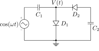
Q13. The diodes and the capacitors in the circuit shown are ideal. The voltage }) across the diode
across the diode  is
is
(A) -1})
(B) })
(C) })
(D) })
Solution
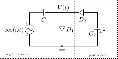
The first half of the circuit is a negative clamper circuit and the second half is a peak detector circuit as shown in the figure below.
(Discussed in Section 3.8 of MicroElectronic Circuits Sedra/Smith (from Amazon.com, from Flipkart.com) or in Chapter 6.17 of Millman’s Electronic Devices and Circuits (from Amazon.com, from Flipkart.com)
The negative clamper circuit works as follows :
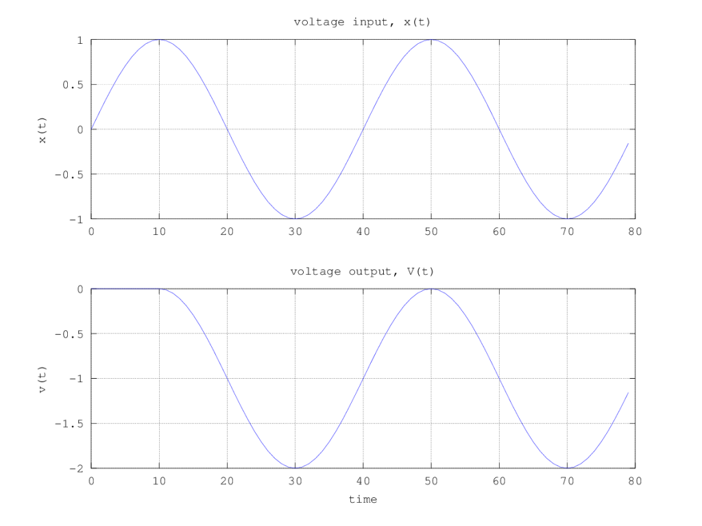
The diode D1 will be initially conducting till the voltage across the capacitor C1 is charged to the peak voltage of 1 volts. In the following cyclesDuring the first half of the +ve cycle, the diode D1 will be ON and the capacitor is charged to peak voltage. The diode D1 will remain OFF during the further cycles and the voltage is given by,
 .
.
The second half of the circuit i.e the peak detector circuit, provides a negative voltage of -2 volts at the output of capacitor C2. Anyhow, given that we are only interested in the output of the negative clamper, the voltage is
Based on the above, the right choice is (A) 1
References
[1] GATE Examination Question Papers [Previous Years] from Indian Institute of Technology, Madras http://gate.iitm.ac.in/gateqps/2012/ec.pdf
[2] MicroElectronic Circuits Sedra/Smith (Buy from Amazon.com, Buy from Flipkart.com)
[3] Millman’s Electronic Devices and Circuits ( Buy from Amazon.com, Buy from Flipkart.com)
For C2 to charge, D2 must be ON. This happens only during the negative cycles of the input. During the positive cycles. D2 is OFF only during the +ve half cycle.
@Pravin: Hope you agree that C2 gets charged to -2volts. Once that happens chances of D2 becoming ON is very less
During the complete positive cycle of the input, D1 is ON making the output 0 for this half-cycle.
In the positive half-cycle, D1 is OFF (can be removed). Now D2 is ON and the voltage V(t) would be the voltage across C2, which is the capacitive division of C1/(C1+C2)*cos(wt) assuming that D2 is ideal. This is definitely not cos(wt) -1.
@Pravin: Well, wont the capacitor C2 gets charged to -2volts, keeping the diode D2 OFF most of the time?