In a post on Minimum Shift Keying (MSK), we had discussed that MSK uses two frequencies which are separated by and phase discontinuity is avoided in symbol boundaries. In that post, we had discussed MSK as a continuous phase transmit signal and showed that phase changes through 0, 90, 180 and 270 degrees. In this post, we will discuss MSK transmission as a variant of offset-QPSK technique. Further, we will discuss the receiver structure and show that bit error rate with coherent demodulation of MSK (using
time) is equivalent to that of BPSK modulation. The channel assumed is AWGN.
MSK transmitter
Using bit-sequence and the explanation provided in the excellent paper Minimum shift keying: A spectrally efficient modulation Subbarayan Pasupathy, IEEE Communications Magazine, July 1979 as a reference, let us proceed as follows:
a) Consider a 8 bit sequence which is BPSK modulated as [+1, +1, -1, -1, -1, +1, +1 , +1] having symbol duration of .
b) The same sequence can be sent over QPSK modulation, where even bits are send on I-arm and the odd bits are send over Q-arm. To keep the same data rate, the bits on the I/Q arm are send for symbol periods.
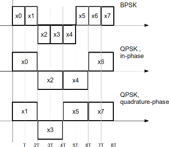
Figure: Transmission of BPSK/QPSK modulation
c) Now, a variant of QPSK called offset-QPSK (O-QPSK) can be generated by having a relative delay between the I-arm and Q-arm by symbol period .
Note: The advantage of O-QPSK is that phase of the signal can jump at a maximum of only 90 degrees (when compared to 180 degrees in QPSK). Having a smaller phase jump ensures that the spectrum of the waveform is cleaner even when there are distortions in the transmitter.
d) Researchers have found that they can make the phase transitions zero, if rectangular pulse shapes used in O-QPSK are replaced by sinusoidal pulse shapes i.e by using and
on the I and Q arm respectively. This is also known as Minimum Shift Keying (MSK) !
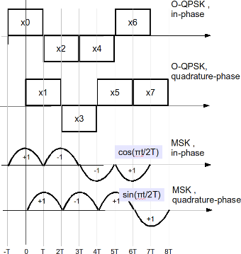
Figure: Transmission of O-QPSK/MSK modulation
Assuming that the carrier frequency is , the MSK transmission can be written as
,
where
are the even pulse sequence (send on the I arm) and
are the odd pulse sequence (send on the Q arm).
Using trigonometric identities, the above equation can also be written as,
,
where
and
.
We can see that MSK can indeed be visualized as a form of frequency shift keying (FSK), where the two frequencies are and
.
Note: This equation is comparable to that described in the post Simulating MSK transmission
The MSK transmitter block diagram is shown below
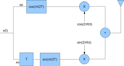
Figure: Block diagram of MSK transmitter
MSK Receiver
The receiver for the MSK transmission can be constructed as follows:
a) Down convert the RF signal to I and Q arms by I/Q down conversion
b) Multiply the I and Q arms by and
respectively
c) Integrate over the a period of
d) On I arm, perform hard decision decoding on the integrator output at every to get the even bits
e) On Q arm, delay by time , perform hard decision decoding on the integrator output at every
to get the odd bits
The block diagram is shown below: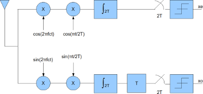
Figure: MSK receiver block diagram
Simulation Model
The Matlab/Octave script performs the following
(a) Generate random binary sequence of +1’s and -1’s.
(b) Group them into even and odd symbols
(c) Perform rectangular pulse shaping on the even and odd symbols, delay the odd symbols by
(d) Multiply the even and odd symbols by and
respectively and transmit
(e) Add additive white Gaussian noise (AWGN) for the given value of
(f) Multiply the I and Q arm by and
respectively and integrate over period
(g) Using the I arm, recover even bits by performing hard decision decoding on integrator output every time
(h) Using the Q arm, recover even bits by performing hard decision decoding on integrator output delayed by time every
time
(i) Count the bit errors
(j) Repeat for multiple values of and plot the simulation and theoretical results.
Click here to download Matlab/Octave script for computing BER with MSK transmission and reception in AWGN channel
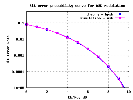
Figure: BER plot for MSK transmission/reception in AWGN channel
Observations
1./ The BER with MSK is identical to BER with BPSK modulation. This is because MSK demodulation in the above simulation is performed by integrating the received symbol over time .
2./ Note that it is indeed possible to demodulate MSK by observing only over time and demodulate it as a FSK with two carriers at
and
. If such a demodulation is performed, then the BER with MSK will be 3dB poorer (comparable to FSK demodulation) when compared to BPSK modulation.
Reference
Minimum shift keying: A spectrally efficient modulation Subbarayan Pasupathy, IEEE Communications Magazine, July 1979
hi krishna i am doing project on msk ,plz help me how i can implepent the circuit diagram plz help me i am troble.
@Fahad: I have written two articles involving MSK. Hope this helps
https://dsplog.com/tag/msk/
Hi, may i know how do you combine the quadrature and the in phase components to view frequency modulated MSK signal.
Thanks
@sree: Extracting from the article:
(f) Multiply the I and Q arm by cos(pi/2T) and sin(pi/2T) respectively and integrate over period
(g) Using the I arm, recover even bits by performing hard decision decoding on integrator output every time
(h) Using the Q arm, recover even bits by performing hard decision decoding on integrator output delayed by time every time
Hi Krishna,
thanks for your comments to msk modulation. I am busy to construct some software solutions for msk decoding.
Looking at your receiver block diagram, the integration over 2T, is this an moving average, sum over 2T samples after every sample, or only every n*2T samples?
Thank you and good luck.
Emil Neumann , Schwerte Germany
@Neumann: A moving average over a window of 2T samples
this was the time intv i was using. The solution you gave me previously is fine for the exp msk version but doesnt work for this one.
time_sampling = [0:1/fs:T];
time_sampling = time_sampling(1:end-1);% gets ride of the final value
%Produces the time intervals
Hi,
I used this equation to modulate MSK
xt = cos(2*pi*(fc+frequency_differance_repeat).*time_sampling_repeated + Phase_value_array_repeat );
This equation is from your website. It works fine.
The i multiplied the received (xt) signal by the following (first stage of the receiver as instructed on your website):
( i hvnt added noise yet)
%even arm
stage1_cos = xt.*(cos(2*fc*pi*time_sampling_repeated)).*(cos(pi.*time_sampling_repeated/2*T));
%odd arm
stage1_sin = xt.*(sin(2*fc*pi*time_sampling_repeated)).*(sin(pi.*time_sampling_repeated/2*T));
How do i recover the signal from here. I’m still having a problem with evaluating the intergtration from 0 to 2T for the above signal.
@Sarah: Well, if your sampling period is 1/Ts, you need to sum over 2T/Ts samples 🙂
I am unable to write the precise code as I do not follow your code well. But am sure that you will be able to figure this out. Good luck.
Just have one more basic question.
in the above steps:
(f) Multiply the I and Q arm by and respectively and integrate over period 2T
if you already have a matrix of numbers in I and Q, how do u actually intergrate it over 2T
@Sarah: The convolution operation with taps as all ones for duration of 2T takes care of the integration of 2T
conv(real(yt).*ct,ones(1,2*T))
Hi,
i was just going thru the code you have written to evaluate MSK receiver. I just have a few questions regarding it. Im currently doing my final year project on this stuff so wondering if u cn help me understand the code better.
In your code this is what you have written:
%% MSK receiver
% multiplying with cosine and sine waveforms
xE = conv(real(yt).*ct,ones(1,2*T));
xO = conv(imag(yt).*st,ones(1,2*T));
bHat = zeros(1,N);
bHat(1:2:end) = xE(2*T+1:2*T:end-2*T) > 0 ; % even bits
bHat(2:2:end) = xO(3*T+1:2*T:end-T) > 0 ; % odd bits
I wanted to know what the last two lines of this is doing. And how u worked out 2*T+1:2*T:end-2*T.
@Sarah: Well,
a) starting from 2T+1 ensures that the first 2T symbols are ignored (to account for the delay of the integration by 2T)
b) the step size of 2T ensures that we take one symbol from the even, then from odd, then even and so on…
hi krishna,
i am comparing the DPSK and MSK modulations to different parameters. Can u please help me in two queries.
1. Is the error performance of BPSK and MSK are similar when MSK is done in sinusoidal wavedorm.
2. How can i extend both the modulations to complex systems such as OFDM.
Can i get a M-file regarding that.
thanks in advance
hi krishna,
i am comparing the DPSK and MSK modulations to different parameters. Can u please help me in two queries.
1. Is the error performance of BPSK and MSK are similar.
2. How can i extend both the modulations to complex systems such as OFDM.
Can i get a M-file regarding that.
thanks in advance
@pradeep:
1/ MSK using received samples integrated over 2T symbol periods will have BER comparable to BPSK. Please refer to the following post
https://dsplog.com/2009/06/16/msk-transmitter-receiver/
2/ I have discussed BPSK in OFDM case. Please refer
https://dsplog.com/2008/06/10/ofdm-bpsk-bit-error/
thanks for ur replay krishna
hi Krishna, can you let me know when most probably you might have time to do that? I am really eager to see it. But anyways, thanks a lot in advance!
@kos: I cannot put a time limit, but maybe in the coming months. I just restarted the posting after around one month of lull and now discussing TETRA specifications
Hi Krishna,
I want to ask you something. Can you explain me why you divide by 20 the ratio Eb/N0 when you want want to add the noise to the signal. In my opinion, the ratio Eb/N0 is like ratio of energy and you have to divide it by 10 isn’t it ?
Thanks in advance.
@Djaybee: Yes, its an energy ratio. However, note that the scaling is applied on a voltage signal. Hence the factor of 20
Hello,
Thanks for your work. I would like have a little more info about the matlab code. In MSK reciever, while retrieving data from the carrier, You have convolve with ones (1,8). Would you please explain, what exactly has been done with this convolution? Is it mandatory for OQPSK modulation?
Thanks in advance
@Marzuk Afgan: The convolution is done to integrate over a period of 2T
hi Krishna, is there any difference between above your implementation and ieee 802.15.4(zigbee) standard’s oqpsk with half-sine pulse shaping? thanks!
@kos: Sorry, I have not looked into the Zigbee standard.
Hi Krishna, http://www.academypublisher.com/ojs/index.php/jcm/article/viewFile/02042937/156
they discuss it in this paper, if you have time can you look at it. My interest is the Figure 4 in that paper. They use also OQPSK but with half-sinusoidal pulse shaping…? I think that if you could modify your MSK transmitter a bit, it should be worked out. Plz, if you have time can you spend some time on this? Thanks a lot in advance!!!
@kos: I had a quick look at the paper. Is it using half sinusoidal pulse shaping? I did not find any text explicitly mentioning that
Hi Krishna, yes it is using half-sine pulse shaping. Thanks a lot for your time spent on this issue. ftp://lenst.det.unifi.it/pub/LenLar/proceedings/2007/ICC2007/DATA/S09S01P05.PDF
in this paper they show it in equation (2). Thanks a lot in advance!
@kos: I was looking at equations (1), (2) in the paper – and they look identical to the MSK waveform. Agree?
Infact, I found a R&S article on Zigbee stating the same http://www2.rohde-schwarz.com/file_1180/1EF55_1E.pdf
Hi Krishna, thanks a lot for your reply. Can you modify msk-transmitter-receiver into one which will be resembling zigbee-transmitter-recevier? Thanks a lot in advance!
@kos: Well, I have not written any post on Zigbee standards till date. Will keep that in the to-do list….
Thanks!
Hi Krishna, when probably you would have time to do that? I am really eager to see that. Anyways, thanks a lot for considering!
Hi Krishna, they also show it in this paper
http://140.116.72.245/~zak/ZigBee/Docs/IEEE802.15.4.pdf
in section 6.5. Thanks a lot in advance!!!
@kos: Ok
Hi Krishna, sorry for several replies, I could not find the edit button. Here is another source
http://books.google.com/books?id=m5NYbUpqXY0C&pg=PA148&lpg=PA148&dq=ieee+802.15.4+%2B+half-sinusoid&source=bl&ots=9gM_xr7Wbk&sig=RnPvx1G5tytRFv3Too2-kR-nNNw&hl=en&ei=QLayS8WOPIa-sgPKyZjdBA&sa=X&oi=book_result&ct=result&resnum=2&ved=0CA8Q6AEwATge#v=onepage&q=&f=false
Thanks a lot in advance!!!
Hi Krishna, yes it is using half-sine pulse shaping. They mention it in the following links:
1) here ftp://lenst.det.unifi.it/pub/LenLar/proceedings/2007/ICC2007/DATA/S09S01P05.PDF they show it in equation 2, also Figure 1 shows how the data is entered to the oqpsk modulator;
2) in this one http://140.116.72.245/~zak/ZigBee/Docs/IEEE802.15.4.pdf they describe it in section 6.5;
3) they also show it here, http://books.google.com/books?id=m5NYbUpqXY0C&pg=PA148&dq=zigbee+%2B+half+sinusoidal&cd=1#v=onepage&q=&f=false
Thanks a lot for spending time on this issue!!!
Hi Krishna, sorry for the fourth reply it is actually the copy of the previous three in one. When I first opened the firefox, it did not show my replies for that reason I thought my replies where deleted… Thanks in advance!!!
@kos: No problem
hi Krishna, thanks for your post. do you have a code for ieee 802.14.5 Physical layer OQPSK with half sine pulse shaping? thanks a lot!
@Riki: Sorry, I do not have. But are you sure that 802.14.5 uses half pulse shaping?
Hello
I’m doing a project for connecting two systems through an MSK modulation scheme in Matlab. Coherent transmission and reception is OK but the reception incoherent does not, you could help me with some idea.
Thanks
@Jose Antonio: You are looking for an in-coherent demodulation of MSK, hmm. I cannot think of anything, but do you have some references? I will try to read up and tell you.
Very useful, and I have a question, because of my knowledge, MSK reveiver is using by Viterbi Algorithm , but…. when I simulated MSK BER using VA , it can produce a big problem , and I don’t know why , can you
give me some suggest,please….
thank you very much
@Wig: For the simulations in this post, I treated MSK as a variant of Offset QPSK and demodulated accordingly. Though I have not tried demodulation using the knowledge of phase transitions and corresponding Viterbi decoding, I believe BER should be matching with curve obtained for BPSK.
Good luck in your algorithm explorations.
sir..i’m working on a paper “typical channel coding and modulation scheme for satellite communication system”.I’n this paper it analyzes the characteristic of the satellite commu. system as well as the satellite communi. channel and introduces the basic principlle and outstanding advantages of cinvolutional code and msk modulation.BER performance of conv. code and msk is simulated with matlab/simulink.the conclusion based on the simulation result provide reference to the design of the satellite communication system…
sir…what modification i can apply on this scheme…and could you please send me the matlab code for msk+convolution using awgn channel..I’ll BE VERY THANKFUL TO YOU…
hi good thank you blog