We have discussed quite a few receiver structures for a 2×2 MIMO channel namely,
(a) Zero Forcing (ZF) equalization
(b) Minimum Mean Square Error (MMSE) equalization
(c) Zero Forcing equalization with Successive Interference Cancellation (ZF-SIC)
(d) ZF-SIC with optimal ordering and
(e) MIMO with MMSE SIC and optimal ordering
From the above receiver structures, we saw that MMSE equalisation with optimally ordered Successive Interference Cancellation gave the best performance. In this post, we will discuss another receiver structure called Maximum Likelihood (ML) decoding which gives us an even better performance. We will assume that the channel is a flat fading Rayleigh multipath channel and the modulation is BPSK.
2×2 MIMO channel
In a 2×2 MIMO channel, probable usage of the available 2 transmit antennas can be as follows:
1. Consider that we have a transmission sequence, for example
2. In normal transmission, we will be sending in the first time slot,
in the second time slot,
and so on.
3. However, as we now have 2 transmit antennas, we may group the symbols into groups of two. In the first time slot, send and
from the first and second antenna. In second time slot, send
and
from the first and second antenna, send
and
in the third time slot and so on.
4. Notice that as we are grouping two symbols and sending them in one time slot, we need only time slots to complete the transmission – data rate is doubled ! 🙂
5. This forms the simple explanation of a probable MIMO transmission scheme with 2 transmit antennas and 2 receive antennas.
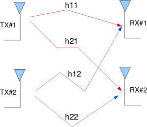
Figure: 2 Transmit 2 Receive (2×2) MIMO channel
Let us now try to understand the math for extracting the two symbols which interfered with each other. In the first time slot, the received signal on the first receive antenna is,
.
The received signal on the second receive antenna is,
.
where
,
are the received symbol on the first and second antenna respectively,
is the channel from
transmit antenna to
receive antenna,
is the channel from
transmit antenna to
receive antenna,
is the channel from
transmit antenna to
receive antenna,
is the channel from
transmit antenna to
receive antenna,
,
are the transmitted symbols and
is the noise on
receive antennas.
We assume that the receiver knows ,
,
and
. The receiver also knows
and
. The unknown s are
and
.
For convenience, the above equation can be represented in matrix notation as follows:
.
Equivalently,
Other Assumptions
1. The channel is flat fading – In simple terms, it means that the multipath channel has only one tap. So, the convolution operation reduces to a simple multiplication. For a more rigorous discussion on flat fading and frequency selective fading, may I urge you to review Chapter 15.3 Signal Time-Spreading from [DIGITAL COMMUNICATIONS: SKLAR]
2. The channel experience by each transmit antenna is independent from the channel experienced by other transmit antennas.
3. For the transmit antenna to
receive antenna, each transmitted symbol gets multiplied by a randomly varying complex number
. As the channel under consideration is a Rayleigh channel, the real and imaginary parts of
are Gaussian distributed having mean
and variance
.
4. The channel experienced between each transmit to the receive antenna is independent and randomly varying in time.
5. On the receive antenna, the noise has the Gaussian probability density function with
with
and
.
7. The channel is known at the receiver.
Maximum Likelihood (ML)Receiver
The Maximum Likelihood receiver tries to find which minimizes,
Since the modulation is BPSK, the possible values of is +1 or -1 Similarly
also take values +1 or -1. So, to find the Maximum Likelihood solution, we need to find the minimum from the all four combinations of
and
.
The estimate of the transmit symbol is chosen based on the minimum value from the above four values i.e
if the minimum is ,
if the minimum is ,
if the minimum is and
if the minimum is .
Simulation Model
The Matlab/Octave script performs the following
(a) Generate random binary sequence of +1’s and -1’s.
(b) Group them into pair of two symbols and send two symbols in one time slot
(c) Multiply the symbols with the channel and then add white Gaussian noise.
(d) Find the minimum among the four possible transmit symbol combinations
(e) Based on the minimum chose the estimate of the transmit symbol
(h) Repeat for multiple values of and plot the simulation and theoretical results.
Click here to download Script for computing BER for BPSK in 2×2 MIMO Rayleigh channel with Maximum Likelihood Equalization
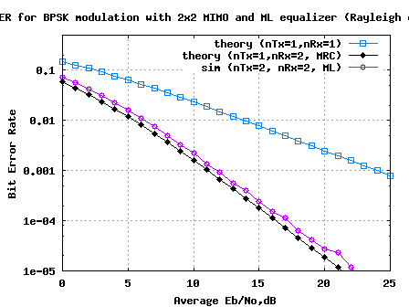
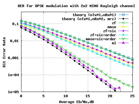
FIgure: BER plot 2×2 MIMO Rayleigh channel with Maximum Likelihood equalisation
Summary
1. The results for 2×2 MIMO with Maximum Likelihood (ML) equalization helped us to achieve a performance closely matching the 1 transmit 2 receive antenna Maximal Ratio Combining (MRC) case.
2. If we use a higher order constellation like 64QAM, then computing Maximum Likelihood equalization might become prohibitively complex. With 64QAM and 2 spatial stream we need to find the minimum from combinations ! In such scenarios we might need to employ schemes like sphere decoding which helps to reduce the complexity.
References
[DIG-COMM-BARRY-LEE-MESSERSCHMITT] Digital Communication: Third Edition, by John R. Barry, Edward A. Lee, David G. Messerschmitt
[WIRELESS-TSE, VISWANATH] Fundamentals of Wireless Communication, David Tse, Pramod Viswanath
Hi Krishna, its a great work done by you, I am trying to modify your code for 3X3 MIMO case everything is fine till i got finding the minimum from the four alphabet combinations , but thereafter I could not understand the part related to mapping the minima to bits
ref = [1 1; 1 0; 0 1; 0 0 ];
ipHat = zeros(1,N);
ipHat(1:3:end) = ref(dd,1);
ipHat(2:3:end) = ref(dd,2);
This I have modified as
ref = [1 1 1; 1 1 0; 1 0 1;1 0 0; 0 1 0;0 0 1;0 0 0];
ipHat = zeros(1,N);
ipHat(1:3:end) = ref(dd,1);
ipHat(2:3:end) = ref(dd,2);
but getting flat response for all Eb/No
Could you elaborate this part
Thanks
@Vaibhav: Are you getting zero BER for no-noise case? One can use that for debugging the code.
Then as you said, one need to find the cost function Jxxx for all the 2^3=8 combinations and then try to find the minima among them.
Hi,
sir you told that For the 2×1 STBC system, the zero forcing equalizer should have given the same performance as ML equalizer, but zero forcing have some disadvantage .so can you provide me a refr. for coding in which ML is use for 2×1 STBC system.
Thank u….
@raj: For 2×1 STBC, the zero forcing equalizer is optimum as there is no interfering term.
Hi mr. khrisna
why we should change 0 into -1? is there any reason?
@sera: that is just to provide two references
Hi Khrisna!
Do you know any equalizer which doesn´t need to know the channel?
@Gidy Florez: Well, am guessing that you are referring to equalizer estimation algorithms.
STBC 2×2 and 2×1 both system receiver use block= antenna— combiner—– ml decoder—-out put(ref by book space time coding branka vucetic, jinhong yuan John Wiley & Sons Ltd)
1. which type combiner use?
2. combiner and ml decoder are same and they work combine
@piyush: For the 2×1 STBC system, the zero forcing equalizer should have given the same performance as ML equalizer
Dear Krishna,
How can we make sur that this results is correct. Is there any theoretical analysis for ML, that we can plot and compare with the simulation??
@Raj: I recall referring to the curve in Digital Communication: Third Edition, by John R. Barry, Edward A. Lee, David G. Messerschmitt.
Hi Krishna!
man i am such a big fan of yourz… your make the incomprehensible seem topics quite easy and understandable.
I am working on blind channel equalization (i am trying to simulate CMA and RCA in MATLAB for time varying, multipath rayleigh channel). just wanted to ask have you tried this domain? can you provide me some guidance in this area? any idea about some good website which may help me in my Matlab simulation of said algos. Its urgent coz I am stuck at some point and couldnt find any way out.
@sara: Thanks. Have not looked into the blind equalization topic, sorry.
Dear Mr. Krishna
I was sent an message to your email. I need your help about this post but use QPSK modulation. Hope you can read my message.
Thank You
@student: hope posts @ https://dsplog.com/tag/psk/ can be of help to you
thanks. I have been able to modify it with qpsk modulation
Hi Krishna.
i want to ask some question about this project.
1. what does “2*ip-1;” means? whether 2 represent number of bpsk constellation?
2. i have tried this program with 3×3 and 4×4 Rx/Tx combination, it’s the result : http://cdn-u.kaskus.us/71/joci0gkv.jpg . is it true?
3. can this program use for qpsk, 16qam, and 64qam constellation?
Thanks for the attention.
@reza: My replies
1. The variable ip is random bits of 1’s and 0’s. The 2*ip-1 maps 1’s to +1 and 0’s to -1 (aka BPSK modulation)
2. Have not tried 3×3, 4×4. Need to check
3. Yes. But need to modify to handle the appropriate modulation
https://dsplog.com/2012/01/01/symbol-error-rate-16qam-64qam-256qam/
thanks for the feedback.
– I have tried for use combination of 1×1 Tx-Rx in this project, but I must get an error in “Channel and noise addition” part. Why?
– Which part should be change for use QPSK modulation beside changing the combination of sHat?
@reza: The post on 1tx-1rx with Rayleigh channel will be of help
https://dsplog.com/2008/08/10/ber-bpsk-rayleigh-channel/
hi Krishna,do you have any code for MIMO OFDM using Sphere Detection?
i’m sorry for my question that out of topic
thank you
@Anky: Will try to write on that topic
oh that’s great
can you spare me some clue to solve this method?
@Anky: clue?
Hi Krishna, Do have any information and matlab code for Semidefinite program (SDP) relaxation detector (optimization problem).
@faisal: Sorry no
Thanks Krishna for quick reply and time
Please can u give 16QAM code instead of BPSK using ML ?
@faisal: I do not have any 16QAM MIMO ML Matlab code handy. But hope the posts on 16QAM can help you to reach the goal
https://dsplog.com/tag/16-QAM/
Thanks Krishna for time and help
can you explain me this lines
EbN0Lin = 10.^(Eb_N0_dB/10);
theoryBer_nRx1 = 0.5.*(1-1*(1+1./EbN0Lin).^(-0.5));
p = 1/2 – 1/2*(1+1./EbN0Lin).^(-1/2);
theoryBerMRC_nRx2 = p.^2.*(1+2*(1-p));
???
@benza :
EbN0Lin = 10.^(Eb_N0_dB/10); % converting log to linear
theoryBer_nRx1 = 0.5.*(1-1*(1+1./EbN0Lin).^(-0.5)); % theoretical value for BER in Rayleigh channel
https://dsplog.com/2009/01/22/derivation-ber-rayleigh-channel/
p = 1/2 – 1/2*(1+1./EbN0Lin).^(-1/2);
theoryBerMRC_nRx2 = p.^2.*(1+2*(1-p)); % theoretical value for BER in Rayleigh channel for 2Rx case
please Mr. Krishna Sankar Iwant to build simple mimo ofdm system to simulate snr vs. ber but I want it the mimo system to be flexable not only 2×2 so ican change the number of transmitter and recievers please help me if you have the matlab code please send it to me
@eng_dina: In most of the articles which I have discussed I have used 2×2 MIMO case. And to increase the speed of the Matlab simulations, I have not used inv() operation in Matlab. You can try using inv() operation and increase the speed of the simulations
I study PAPR REDUCTION for MIMO-OFDM. AND I need matlab code for papr reductıon for MIMO-ofdm. ıf you have any matlab code for thıs subject, please send me…… pls…
@murat: Sorry, I have not tried to do much on PAPR reduction on OFDM systems. If needed you may refer to some posts on PAPR @ https://dsplog.com/tag/papr
Why is my comment deleted ??
Hi,
I have already read your articles about the ZF, MMSE and ML detection methods in MIMO.
I wish to know whether the ML solution for Y = HX+Z (either X or H to be unknown) has a closed form expression or not. Although I know it does not, but of my surprise is that I have come across some papers indicating that the ML solution for the above equation has a closed form similar to what you have mentioned in ZF equalization. Is ZF method equivalent to ML?
@Vahid: I believe the ZF solution is equivalent to ML only if the channel is orthognonal. In other cases, ML is able to combat the interference terms, whereas ZF does not do a good job at that.
hi,
can u just tell me that whether ur matlab code for ml equalisation utilises viterbi algorithm aur something else??
please reply it is really very important.
thanks
@deepak: This code uses brute-force ML (no Viterbi)
please reply my massege it’s really important
thanks
Idon’t try to simulte cfo for mimo system only but for mimo ofdm I propose a new scheme that targets MMIO OFDM systems which have unsynchronized oscillators such that CFO of individual paths have to be estimated separately. This scheme may also apply to OFDM systems with multi-user access. The new method, which is similar to Moose’s method, estimates the CFO by measuring the carrier phase difference between 2 identical successive training sequences embedded in the preambles. In order to make CFO estimates be more time efficient,I allow 2 transmitter antennas transmit their training sequence concurrently in every time period, except the first and the last period. I use Frank-Zadoff code with different phase shifts in the training sequences in different antennas. Due to the good correlation property of Frank-Zadoff code, it helps reduce the interference caused by the concurrent transmissions from other antennas.
cfo for mimo only but for mimo ofdm system
please helpppppppppppppppppppppppp
Idon’t try to simulte cfo for mimo only but for mimo ofdm system After examining some synchronization I propose a new scheme that targets MMIO OFDM systems which have unsynchronized oscillators such that CFO of individual paths have to be estimated separately. This scheme may also apply to OFDM systems with multi-user access. The new method, which is similar to Moose’s method, estimates the CFO by measuring the carrier phase difference between 2 identical successive training sequences embedded in the preambles. In order to make CFO estimates be more time efficient,I allow 2 transmitter antennas transmit their training sequence concurrently in every time period, except the first and the last period. I use Frank-Zadoff code with different phase shifts in the training sequences in different antennas. Due to the good correlation property of Frank-Zadoff code, it helps reduce the interference caused by the concurrent transmissions from other antennas.
please helpppppppppppppppppppppppp
Idon’t try to simulte After examining some synchronization I propose a new scheme that targets MMIO OFDM systems which have unsynchronized oscillators such that CFO of individual paths have to be estimated separately. This scheme may also apply to OFDM systems with multi-user access. The new method, which is similar to Moose’s method, estimates the CFO by measuring the carrier phase difference between 2 identical successive training sequences embedded in the preambles. In order to make CFO estimates be more time efficient,I allow 2 transmitter antennas transmit their training sequence concurrently in every time period, except the first and the last period. I use Frank-Zadoff code with different phase shifts in the training sequences in different antennas. Due to the good correlation property of Frank-Zadoff code, it helps reduce the interference caused by the concurrent transmissions from other antennas.
cfo for mimo only but for mimo ofdm system
please helpppppppppppppppppppppppp
Hello sir,
i am new to simulation. i want to simulate uplink multiuser MIMO-OFDM detection. i have to do this for LS, MMSE, SIC, V-BLAST and ML. BER comparision and complexity comparision has to be done.
Users have only single antenna and BS has multiple antenna.
my system model is as follows- first generate data then mapping (i m using BPSK ) then serial to parallel converter then ifft (i m taking size-128) then cp (i m taking 10% of ifft size) then parallel to serial then transmit it. i have doubt in all the bracket values why and what value should we choose?
I have to transmit this multiple user data through Rayleigh frequency selective fading channel. how to generate this channel?
and at the BS should we use OFDM demodulation just before MUD block at each receive antenna?
Sir please help me?and Kindly give me steps and approach for simulation?
hi,
your site has been very useful to me. thank u so much. but i have a question abt the MIMO ML Equalizer matlab code.
what does ipHat(1:2:end) = ref(dd,1) do/mean? i am new with matlab.
thanks
@doris: Based on which variable minimized the error, am picking the data bits accordingly.
thank you for reply,sir
Is there any formula or program to count number of multipliers and division to form an estimate of complexity?
how can we measure the diversity orders of all these detectors?
Should i get program or formula for maximum likelihood (ML) with sphere decoder(SD)?
my great pleasure for your reply,
bye.
@raj: My replies
1/ Hand calculate 😉
2/ Based on the BER performance, one can get an estimate. Please refer text books for precise details
3/ I have not yet discussed sphere decoding.
Ok sir,
but should i have to calculate operations based on mathematics? and suppose if i am sending 1000000 sybols, than operations have to multiply with 1000000 or not?
i have read somewhere that the slope of BER vs SNR gives diversity order, is it true? and which book give the detail regarding to diversity order?
@raj: You can try to pick up
a) Fundamentals of Wireless Communication, David Tse, Pramod Viswanath
b) Digital Communication: Third Edition, by John R. Barry, Edward A. Lee, David G. Messerschmitt
Happy dipavali & happy new year sir,
Thanks for giving me the equation for inverse of 4*4 matrix, i m still not apply it, but it will work surely, but the complexity may also incresed so,
1. How can i measure the complexity?
2. Which operations have to considering during complexity calculation?
once again greate thx for helping me.
bye
@raj: Happy dipavali.
1/ You can count the number of multipliers and division to form an estimate of complexity
2/ Multipliers and divisions
hi krishna.
i am doing project on mimo so please if possible provide me a ml detect code .
i wanna m file.
thx
hi krishna
i am doing project on mimo ofdm so please if possible provide me a code at ml detector. i wanna m file
thx
@park: Using this ML code as a reference, you might be able to overlay an OFDM tx-rx on top of this. Good luck.
Hi Krishna Pillai,
I hope you are OK,
Could you help me how I can can derive the BER of SC-FDMA system?
Thanks,
faisal
@Faisal: The SC-FDMA is close to OFDM, no? So, wont the BER of underlying modulation scheme hold good?
Sir, the inverse of 2*2 matrix is 1/(ad-bc) [d -b: -c a],
I am search lot but i am not getting the inverse of 4*4 matrix, so please can you tell me what is inverse of 4*4 matrix and whts the procedure to obtain it?
@raj: From a quick googling, found the following page. It discuss inverse of a 4×4 matrix
http://www.cvl.iis.u-tokyo.ac.jp/~miyazaki/tech/teche23.html
Thanks for your sharing..It’s really useful for understanding ML decoder in order to decode for MIMO cases.
If possible, can you show us how a linear orthogonal decoder works?
Thanks a lot!
@Coldfish: Can you plz give me an example of linear orthogonal decoder.
As far as I know, orthogonal space-time codes can be decoded with a linear orthogonal decoder. I am not %100 percent sure but in spite of using ML decoder at the receiver, we can use the equivalent H channel matrix to decode the symbols. If the code matrix is an orthogonal design, without using all combinations of matrix (ML decoder), we can decode as well with equivalent H matrix easily.
Specifically, I stated that how we can decode OSTBC and QOSTBC designs? Is it possible to give some examples about that? I think QOSTBC are decodable with Pairwise ML decoder.
@Coldfish: Yes, if the code is orthogonal we can do with linear equalizer (as we discussed in STBC case, https://dsplog.com/tag/stbc). I have discussed only a simple Alamouti case, which is an orthogonal code. I need to read up more on non-orthogonal STBC cases and QOSTBC (Q for Quasi?).
Its me again! Thanks for all your wonderful help!! Based on your MIMO 2×2 codes, apparently it cannot work if i just change the nTX & nRX if say i want to do for 4×4 scenario. Is it possible to modify your codes to fit 4×4 or will it be extremely tough? Pls advise!!Thank u!!
@Sivam: By simply changing nTx, nRx to 4 wont enable a 4×4 MIMO scenario. Reason being, the equalizer which is currently an inversion of a 2×2 channel does not scale up gracefully. When changing to a 4×4 MIMO link, pay close attention to the equalizer part. Good luck.
Hi!
Can you describe the sphere decoding algorithm in detail?
(Or as an m file?)
@Kon: I have not yet discussed Sphere decoding. I will add that to the to-do list
hi, have you thought about if the modulation scheme of one of the transmiter is unknown, how can I calculate the BER? Here is something with modulation classification.
@Bob: Well, if we do not know the type of modulation, it might be a bit too difficult, no? In general, we know the modulation type ie. BPSK/QPSK/QAM etc and based on that information, we define the demodulation structure.
Btw, am curious: can you plz specify some more details about the scenario in which were the modulation scheme of the transmitter is unknown at the receiver. Thanks.
Hi Krishna Pillai,
Thanks a lot for your sequence of knowledge about MIMO receivers.
As your results about different methods, it can be seen that receive diversity with MRC gives better performance than any kinds of MIMO receiver (ZF, ZF SIC, MMSE, MMSE SIC, ML), is it right? Pls explain me about this.
@Chi Pham: Well, I do not think that the statement “it can be seen that receive diversity with MRC gives better performance than any kinds of MIMO receiver” – is correct. Receive diversity with MRC is applicable even in non-MIMO cases also, for eg, 1 transmit 2 receive MRC case.
Hey sir,u have sed dat for mimo 1 has to pair up data n den transmit it,cant we send a copy of data at both transmitters and den at da detectr side select the bit with more power u can say,is it da right approach or not??
@maya: Typically, sending the same information from two transmit antennas at the same time does not provide benefits. The approach which you said can be done at the receiver, if we have more than one receive antenna. The post on selection diversity briefly touches on this aspect.
https://dsplog.com/2008/09/06/receiver-diversity-selection-diversity/
Hi
with regard to 2×2 MIMO with ML eqaulization what the changs in the simulation code if there are 8 transmit antenna instead of 2.
Thank you
@yazeed: Does 8 trnamsit antennas mean 8 parallel data streams? In that case, the complexity of the ML increases alarmingly
isntead of BPSK what about QPSK
@yaxeed: Did you mean, you would want to find out the result, if we use QPSK instead of BPSK. Good luck in your algorithm explorations.
In reshape matrix i think that sMod size and [ntx,nrx,N/ntx] size should be same ,sMod size is 1000000 but [ntx,nrx,N/ntx] size is 2000000 .how is it possible ..what is the use of squeeze
@ramu: sMod is a three dimensional matrix. The squeeze function enables us to remove one of the dimensions in an n-dimensional matrix.
I’m concerning about mimoML on time and frequency selective fading, could you give me some tips? Thank you very much!
@lily: The simulations which I provided above are for flat fading time invarient channel. I have not worked much on MIMO with time/frequency selective fading channel.
Hello,
Could you explain how we can calculate the min J if we use 16QAM instead of BPSK?
Thanks,
Ilhami
@ilhami: For 16-QAM it becomes a bit exhaustive. For each spatial dimension, there are 16possible inputs. So, with 2 spatial streams, we need to find the minimum from 16^2 = 256 combinations.
Hello I must simulated the influence of BER in WLAN. Could you help me with some books? tutorial? I must simulat in a program called ADS (Advanced System Design). PLs help. contact me on me email address. 10x
@ Grigoras Christian: Simulation of BER in WLAN should be reasonably easy. I do not have faimiliarity with ADS. You may look at some posts on OFDM @
(a) https://dsplog.com/tag/ofdm
(b) Post on Mathworks simulating 802.11a WLAN in Simulink.
http://www.mathworks.com/matlabcentral/fileexchange/3540
Hope this helps. Good luck.
i am doing project on mimo ofdm so please if possible provide me a code
@shravani: Sure, will do write up on MIMO OFDM infuture.
please suggest a code for MIMO OFDM
@shravani: I have not posted on MIMO plus OFDM. Seems to be a good addition. I will add that.
hi sravani
i am also doing project on mimo ofdm.
what is your project title. so that we can discuss on this.
Hi,
Can you please show what changes to do in your codes in order to get Symbol Error Rate instead of BER?
Thank you!
@Liran: Depends on the modulation scheme. For BPSK, BER is equal to symbol error rate. For higher order modulations symbol error can result in multiple bit errors (depending on the bit assigned to each symbol). For finding the symbol error rate, we define decision boundaries around each symbol. When ever the received symbol is outside the boundary, then the symbol is in error.
You may look at some posts on QAM symbol error rate calculation in AWGN for reference.
Symbol Error Rate (SER) for QPSK (4-QAM)
Symbol Error Rate (SER) for 16-QAM
Hope this helps.
very good
useful
very good