In previous posts, we have discussed convolutional codes with Viterbi decoding (hard decision, soft decision and with finite traceback). Let us know discuss a block coding scheme where a group of information bits is mapped into
coded bits. Such codes are referred to as
codes. We will restrict the discussion to Hamming
codes, where 4 information bits are mapped into 7 coded bits. The performance with and without coding is compared using BPSK modulation in AWGN only scenario.
Hamming (7,4) codes
With a Hamming code, we have 4 information bits and we need to add 3 parity bits to form the 7 coded bits. The can be seven valid combinations of the three bit parity matrix (excluding the all zero combination) i.e.
.
The coding operation can be denoted in matrix algebra as follows:
where,
is the message sequence of dimension
,
is the coding matrix of dimension
,
is the coded sequence of dimension
.
Using the example provided in chapter eight (example 8.1-1) of Digital Communications by John Proakis , let the coding matrix be,
.
This matrix can be thought of as,
,
where,
is a
identity matrix and
is a
the parity check matrix.
Since an identity matrix, the first
coded bits are identical to source message bits and the remaining
bits form the parity check matrix.
This type of code matrix where the raw message bits are send as is is called systematic code.
Assuming that the message sequence is , then the coded output sequence is :
, where
,
,
.
The operator denotes exclusive-OR (XOR) operator.
| Sl No | m0 | m1 | m2 | m3 | p0 | p1 | p2 |
| 0 | 0 | 0 | 0 | 0 | 0 | 0 | 0 |
| 1 | 0 | 0 | 0 | 1 | 0 | 1 | 1 |
| 2 | 0 | 0 | 1 | 0 | 1 | 1 | 0 |
| 3 | 0 | 0 | 1 | 1 | 1 | 0 | 1 |
| 4 | 0 | 1 | 0 | 0 | 1 | 1 | 1 |
| 5 | 0 | 1 | 0 | 1 | 1 | 0 | 0 |
| 6 | 0 | 1 | 1 | 0 | 0 | 0 | 1 |
| 7 | 0 | 1 | 1 | 1 | 0 | 1 | 0 |
| 8 | 1 | 0 | 0 | 0 | 1 | 0 | 1 |
| 9 | 1 | 0 | 0 | 1 | 1 | 1 | 0 |
| 10 | 1 | 0 | 1 | 0 | 0 | 1 | 1 |
| 11 | 1 | 0 | 1 | 1 | 0 | 0 | 0 |
| 12 | 1 | 1 | 0 | 0 | 0 | 1 | 0 |
| 13 | 1 | 1 | 0 | 1 | 0 | 0 | 1 |
| 14 | 1 | 1 | 1 | 0 | 1 | 0 | 0 |
| 15 | 1 | 1 | 1 | 1 | 1 | 1 | 1 |
Table: Coded output sequence for all possible input sequence
Hamming Decoding
Minimum distance
Hamming distance computes the number of differing positions when comparing two code words. For the coded output sequence listed in the table above, we can see that the minimum separation between a pair of code words is 3.
If an error of weight occurs, it is possible to transform one code word to another valid code word and the error cannot be detected. So, the number of errors which can be detected is
.
To determine the error correction capability, let us visualize that we can have valid code words from possible
values. If each code word is visualized as a sphere of radius
, then the largest value of
which does not result in overlap between the sphere is,
where,
is the the largest integer in
.
Any code word that lies with in the sphere is decoded into the valid code word at the center of the sphere.
So the error correction capability of code with distance is
.
In our example, as , we can correct up-to 1 error.
Parity Check Matrix
For any linear block code of dimension, there exists a dual code of dimension
. Any code word
is orthogonal to any row of the dual code. For the chosen coding matrix
, the dual code
is,
.
It can be seen that modulo-2 multiplication of the coding matrix with the transpose of the dual code matrix
is all zeros i.e
.
This dual code is also known as parity check matrix.
Maximum Likelihood decoding
A simple method to perform maximum likelihood decoding is to compare the received coded sequence with all possible coded sequences, count the number of differences and choose the code word which has the minimum number of errors.
As stated in Chapter 8.1-5 of Digital Communications by John Proakis, a more efficient way (with identical performance) is to use the parity check matrix .
Let the system model be,
, where
is the received code word of dimension
,
is the raw message bits of dimension
,
is the raw message bits
,
is the error locations of dimension
.
Multiplying the received code word with the parity check matrix,
.
The term is called the syndrome of the error pattern and is of dimension
. As the term
, the syndrome is affected only by the error sequence.
Lets assume that the message sequence
.
The code output sequence is
Let us find the error syndrome for all possible one bit error locations.
| Sl N0 | c0 | c1 | c2 | c3 | c4 | c5 | c6 | s0 | s1 | s2 | |
| 0 | 0 | 0 | 0 | 0 | 0 | 0 | 0 | 0 | 0 | 0 | |
| 1 | 1 | 0 | 0 | 0 | 0 | 0 | 0 | 1 | 0 | 1 | |
| 2 | 0 | 1 | 0 | 0 | 0 | 0 | 0 | 1 | 1 | 1 | |
| 3 | 0 | 0 | 1 | 0 | 0 | 0 | 0 | 1 | 1 | 0 | |
| 4 | 0 | 0 | 0 | 1 | 0 | 0 | 0 | 0 | 1 | 1 | |
| 5 | 0 | 0 | 0 | 0 | 1 | 0 | 0 | 1 | 0 | 0 | |
| 6 | 0 | 0 | 0 | 0 | 0 | 1 | 0 | 0 | 1 | 0 | |
| 7 | 0 | 0 | 0 | 0 | 0 | 0 | 1 | 0 | 0 | 1 |
Table: Syndrome for all possible one bit error locations
Observations
1. If there are no errors (first row), the syndrome takes all zero values
2. For the one bit error, the syndrome takes one among the valid 7 non-zero values.
3. If we have more than one error locations, then also the syndrome will fall into one of the 8 valid syndrome sequence and hence cannot be corrected.
Simulation Model
The Matlab/Octave script performs the following
(a) Generate random binary sequence of 0’s and 1’s.
(b) Group them into four bits, add three parity bits and convert them to 7 coded bits using Hamming (7,4) systematic code
(c) Add White Gaussian Noise
(d) Perform hard decision decoding
(e) Compute the error syndrome for groups of 7 bits, correct the single bit errors
(f) Count the number of errors
(g) Repeat for multiple values of and plot the simulation results.
Click here to download [download id=”1″]

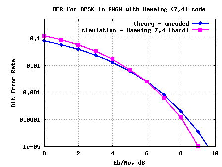
Figure: BER plot for Hamming (7,4) code with hard decision decoding in AWGN
Observations
1. For above 6dB, the Hamming (7,4) code starts showing improved bit error rate.
Reference
Digital Communications by John Proakis


Hi Krishna
Nice work. Please can you reload the code again for Hamming (7,4) code with hard decision decoding. Because the matlab/octave code link is given an error message that it does not exist. Thank you
@Olaolu: Thanks. Fixed the download error – please check now.
krishna thanks for this wonderdul blog!Is it possible a post about Reed-Solomon codes…?will be a perfect add to coding issues discussed here.Again thnks!
I don’t know how to determine bitIdx.
I’m making a code for (23,12)Golay code, and in matlab, “??? Index exceeds matrix dimensions.” this error message coming up. Please help me.
Thanks.
@YH: The variable bitIdx stores the index of the bit to correct. i.e if syndrome is 1 –> 7th bit in error and so on
Hi Krishna,
I understand how you use this line: bitIdx = [7 6 4 5 1 3 2].’; but I am trying to write similar code for a 5×10 regular parity-check matrix where each variable node is connected to 2 check nodes and I don’t know how implement the “bitIdx” vector when there are 2 or more bits in error for a certain syndrome. Do you have any ideas?
Regards,
Conor
@Conor: Well, one can make a decimal number constructed from the two bit location to be flipped. And from the decimal number, get the bit locations. Anyhow, its a matter of coding choice which one wants.
Hi krishna,
Actually, I now know the answer for my second question above. But, since I want to calculate FER (the percentage of codewords in error) as well I can’t flip the parity bits. Is the anyway out to avoid indexing with zero.
Also, when I compare your simulation curve with Matlab generated BER (bercoding(0:10,’Hamming’,’hard’,7)), there is some small difference there. Matlab gives better BER?. Why? Is there a difference?
One last question, We’re treating all error patterns as if they all were of weight one. This way if an error of another weight happens then aren’t we increasing the BER by treating it like it was only one bit in error?
Thank you.
@Jane: My replies
a) Oh, i will check my numbers against bercoding(0:10,’Hamming’,’hard’,7). Am not expecting any delta (unless ofcourse, there are any hidden bugs in the simulation model) 🙂
b) For every one bit error, the syndrome takes one of the 7 non-zero values. If there are more than one-bit error, this code cannot detect.
Hi Krishna,
What if I form my parity check matrix in a way so that the decimal value of syndrome be equal to the location of the bit in error? Like this:
H = [0 0 0 1 1 1 1;0 1 1 0 0 1 1 ;1 0 1 0 1 0 1]
Can I do that?
Could you explain this line as well please:
syndromeDec(find(syndromeDec==0)) = 1;
Why you’re assuming that if no error has happened then we should flip the 7th coded bit?
Also, if we want to calculate the error rate for the codewords (FER) then I think we should count in the errors in parity bits too. Right?
Thank you
@Jane: My relies
a) I think one can do that. The underlying goal is to figure out the error location.
b) Was looking at the comment, and it states something about preventing simulation crash.
syndromeDec(find(syndromeDec==0)) = 1; % to prevent simulation crash, assigning no error bits to parity
I vaguely recall about flipping the parity bit, but it does not have any impact on the BER simulation because the parity bits are anyhow removed prior to BER computation.
If you wish, you can remove that piece of code and tailor it to your needs.
Hey bro can you please upload a Matlab simulation for (15,11) Hamming coding to a BPSK modulated signal which is transmitted in AWGN channel.
@Kamal: Will keep that in the to-do
thank you very much bro… it’s a big help because I could not find any code to do this thing 🙂 thank you again… 🙂
Dear Krishna Sankar!
In Mulation section, we use OPQSK then how we can do?
Thanks!
@phomgk85: Did you mean you want to use OQPSK with Hamming code (instead of BPSK)?
YEAH.
i finding how estimate ber over O-QPSK and AWGN channel using haming 7,4 or hamming 15, 11?
@phongka85: I have not discussed O-QPSK explicitly in the posts…the closest which I came to is MSK
https://dsplog.com/2009/06/16/msk-transmitter-receiver/
Hi,
can anyone please help how to do the program for BPSK coded system (gaussian channel noise) using ML decision at the decoding part.
@Justin: By ML, I reckon you are referring to a soft decision brute force search. I am in the process of finishing up the write up for that. Will have a post on that this week
Hi Krishna,
I like the way you have put together this website. Very nice. May I ask what program you use to create you math pages.
I want to convert my site to a blog style as well.Pperhaps you can suggest someone to convert my website?
Thanks, C. Langton
@charan:
Thanks much for the kind words. I refer to http://www.complextoreal.com a lot for my studies.
For the blogging platform, used WordPress and purchased Thesis theme for the styling. The equations were possible thanks to Mimetex
http://www.forkosh.com/mimetex.html
Hi ,
is any boduyhas workd or ca nhelp me on Linear Block code (15 ,11) using Viterbi decoding ..i want to wrtie a matlab program for it but i am facing some problems in the long and complex trellis stucture …please email to me if somebody can help..thanks
//my implementation in c (not be severely)
//Hamming(7,4) code in BAWGN channel with Hard desigion
//The result is a table of EbNo vs BER
//all worked
//Powered by Pawelitel in 2010
#include
#include
#include
//white gaussian noise
double wgn(void)
{
float PI=3.14159265358;
static int _sw = 0;
static double _t, _u, _x;
if ( _sw == 0 )
{
_sw = 1;
_x = (1.0 / (RAND_MAX + 1.0)) * rand();
while (!_x)_x = (1.0 / (RAND_MAX + 1.0)) * rand();
_t = sqrt(-2 * log(_x));
_u = 2.0 * PI * ((1.0 / (RAND_MAX + 1.0)) * rand());
return _t*cos(_u);
}
else
{
_sw = 0;
return _t*sin(_u);
}
}
int main(int argc, char **argv) {
const int Hamming74EncodeTable[16] = {0 ,14 ,21 ,27 ,35 ,45 ,54 ,56 ,71 ,73 ,82 ,92 ,100 ,106 ,113 ,127};
const int Hamming74DecodeTable[128] = {0 ,0 ,0 ,4 ,0 ,2 ,1 ,8 ,0 ,9 ,1 ,3 ,1 ,5 ,1 ,1 ,0 ,2 ,10 ,3 ,2 ,2 ,6 ,2 ,7 ,3 ,3 ,3 ,11 ,2 ,1 ,3 ,0 ,4 ,4 ,4 ,12 ,5 ,6 ,4 ,7 ,5 ,13 ,4 ,5 ,5 ,1 ,5 ,7 ,14 ,6 ,4 ,6 ,2 ,6 ,6 ,7 ,7 ,7 ,3 ,7 ,5 ,6 ,15 ,0 ,9 ,10 ,8 ,12 ,8 ,8 ,8 ,9 ,9 ,13 ,9 ,11 ,9 ,1 ,8 ,10 ,14 ,10 ,10 ,11 ,2 ,10 ,8 ,11 ,9 ,10 ,3 ,11 ,11 ,11 ,15 ,12 ,14 ,13 ,4 ,12 ,12 ,12 ,8 ,13 ,9 ,13 ,13 ,12 ,5 ,13 ,15 ,14 ,14 ,10 ,14 ,12 ,14 ,6 ,15 ,7 ,14 ,13 ,15 ,11 ,15 ,15 ,15};
float count=pow(10,6);//number of tests
float countfrom=0,countto=count, countstep=1,c=0;
float noiseRootMeanSquare;
float S=1,//signal level
SNR,//energy per signal
EbNo,//energy per bit
simBER=-11.0;
int i,j,l,nErr=0,errorBits,s;
float fin;
const int numberOfBits=4;
const int numberOfCodedBits=7;
int inUncoded,inCoded,outUncoded,outCoded;
float syndroms[numberOfCodedBits];
///compute BER
for ( c=countfrom; c<countto; c+=countstep)
{
SNR=11-c/10.;///SNR from 11dB down with step 1/10 dB
noiseRootMeanSquare=pow(10,-SNR/20.);
EbNo=simBER=nErr=0;
for ( i=0; i<count; i++ )
{
inUncoded=rand()%16;
inCoded=Hamming74EncodeTable[inUncoded];
outCoded=0;
for ( j = 0; j < numberOfCodedBits; j++ )
{
s=(inCoded&(1<0;/// 0 или 1
syndroms[j]=2*s-1+1/sqrt(2)*noiseRootMeanSquare*wgn();///BAWGN
outCoded ^=(syndroms[j]>0)<<j;//hard decision
}
outUncoded=Hamming74DecodeTable[outCoded];
errorBits= inUncoded ^ outUncoded;
if (errorBits)
for ( l=0; l<numberOfBits; l++ )
if (errorBits&(1<<l))
nErr++;
}
SNR = 20*(log10(S/noiseRootMeanSquare));
EbNo = SNR – 10*log10(numberOfBits/float(numberOfCodedBits));
printf("%f ",EbNo);
simBER=log10(nErr/float(count*numberOfBits));
printf("%f\n",simBER);
if (EbNo<0)break;
}
return 0;
}
@Pawelitel: The above code works as intended? Great. People who needs C code can take this 🙂
Mr. Krishna ,
always thank you for very helpful posts. sorry for question not related to post. i am new in this field,especially in mathlab. so t is the best way to learn writing code in Mathlab. if you have any sugesstion? any suggestion will be appreciated.
thanks you
Hi Krishna,
I would like to Hamming code (7,4) into qpsk modulation and demodulation system? what should I do? thanks.
@victor: Well, that should be simple.
You can group two coded bits into a QPSK, add awgn noise, demap into bits, then hamming decode
You can use this code as reference for qpsk mapping and demapping
https://dsplog.com/2007/11/06/symbol-error-rate-for-4-qam/
Plz help me
Actually I want to know the steps calculate hamming codes use hamming 7/4 mechanism
@thilini: Hopefully, this post discuss all the details which you require. Good luck.
I’m creating a 15 11 hamming code and I just want to know how you chose bitIdx=[7 7 4 7 1 3 2] for your 7 4 hamming code. I desperately need help. THANK YOU SO MUCH!
my
h=[1 0 0 1;1 0 1 1;1 1 1 1; 0 1 1 1;1 1 1 0;0 1 0 1; 1 0 1 0; 1 1 0 1;0 0 1 1;0 1 1 0; 1 1 0 0];
ht=[h; eye(4)];
g=[eye(11) h];
synRef = [9 11 15 7 14 5 10 13 3 6 12];
@linda: Instead of giving you the answer, may I give you the steps. I guess, it should be easy for you to figure this out.
For each coded output sequence c = mG, try multiplying with the parity check matrix H^T.
For no errors in c, the operation mGH^T = all zeros.
Introduce one bit error in c, the operation mGH^T will result in a non-zero matrix. Observe the location of the non-zero element and use it find out which bit is in error.
Good luck.
hy sir please could you send me hard decession decoding with orthogonal signals for linear block code
@Saiful: Sorry, I do not have codes for that.
Hi Krishna,
would you please help me in writing the same code using matlab functions?
Thanks
@New_Student: Sorry, I do not have the Matlab functions. It should be much much easier to write it that way, no? Good luck.
I am wondering how can i use your code using MATLAB function for Hamming to find BER and final graph?
[ encoded_msg=encode(tmsg,7,4,’hamming/binary’)
decodeed_msg=decode(rmsg,7,4,’hamming/binary’) ]
I think error correction is taken care by matlab if we use this functions and so no need for g, h and synd. Am i right? Can you tell me more about any need of preshaping the binary matrix before encoding? after decoding?
Why didn’t you use MATLAB functions in the first place?
Sorry for many questions but I like your work and I know you have all the answers.
Thanks for your wonderful work and tons of help to me and all.
God bless you.
@Richard: If we use matlab functions, then there is no fun in learning … 😉
I try to use only the most basic matlab functions and then code the rest of the blocks using those basic set.
Thanks for the clarification Krishna,
Have you done the block coding simulation using RS codes in matlab? Can you point me to example code?
@Tahmid: Sorry, not done RS codes till date.
sorry I can’t understand a row of your program code:
bitIdx = [ 7 7 4 7 1 3 2].’; 7 7 4 7 1 2 3 ???
↑↑↑↑↑↑↑↑↑↑↑↑↑↑↑↑↑↑↑↑↑↑↑
Could u tell me why do that,please~? my brain can’t figure out it~
thanks!!!
@Wig: Its related to the syndrome and the location of the bit which is in error. For eg, with
synRef = [ 5 7 6 3 ];
bitIdx = [ 7 7 4 7 1 3 2].’;
With syndrome of 5, the 1st bit is in error
With syndrome of 7, the 2nd bit is in error
With syndrome of 6, the 3rd bit is in error
With syndrome of 3, the 4th bit is in error
The rest of the incides we can ignore, as we do not count the errors in parity bits for our raw BER computation. Helps?
I understand
synRef = [ 5 7 6 3 ];
With syndrome of 5, the 1st bit is in error
With syndrome of 7, the 2nd bit is in error
With syndrome of 6, the 3rd bit is in error
With syndrome of 3, the 4th bit is in error
but I do not understand how you got this from synRef
bitIdx = [ 7 7 4 7 1 3 2].’;
Could you please explain that? Thanks
@Linda: The variable bitIdx stores the index of the bit to correct. i.e if syndrome is 1 –> 7th bit in error and so on
Am not using synRef in the simulation (maybe I forgot to remove it while doing the code cleanup)
Hi Krishna,
Could you explain more about the variable bitIdx?
Why if syndrome is 1 –> 7th bit in error ?
Could you give more examples like if syndrome is 6, what the bitIdx will be?
Thanks.
@sophia: The bitIdx is used to identify the bit to correct based on the syndrome value. If syndrome is 6, the bit in error is 3. The full list is given in “Table: Syndrome for all possible one bit error locations”
Hi Krishna,
If you were to do this over Rayleigh channel you would the following?
1. multiply message with
h = 1/sqrt(2)*[randn(size(cip)) + j*randn(size(cip))];
2. then divide the faded signal by h
3. demodulate
@Tahmid: In general yes. To be more precise:
1/ Generate random bits
2/ Code as per (7,4) Hamming code
3/ Convert to constellation symbols
4/ Multiply with channel h and add noise (awgn)
5/ Equalize at the receiver by dividing by h
6/ Do hard decision decode and find received coded bits
7/ Do Hamming decode and find received raw bits.
Good luck.