In signal processing blocks like power estimation used in digital communication, it may be required to represent the estimate in log scale. This post explains a simple linear to log conversion scheme proposed in the DSP Guru column on DSP Trick: Quick-and-Dirty Logarithms. The scheme makes implementation of a linear to log conversion simple and small in a digital hardware like FPGA.
Consider an integer . The floating point representation is,
where,
is the exponent and
is the mantissa.
Assume that is normalized, i.e
.
Taking logarithm to the base 2,
.
In digital hardware implementations, finding the exponent is simple. Its just noting the index of the first bit which is 1 starting from MSB side.
For example consider an input number .
Expressed in binary on 8 bit bus, .
The value of in this example is 3.
Now, the part which remains to be computed is the mantissa . In this example,
.
Given that lies in the range
. this can be computed using a Look Up Table. The LUT can store
values of input between 1 to 2. The precision requirement determines the number of elements in the LUT. Let us assume that we want to have a precision of
, where
. The look up table values will be as follows:
| k=4 | ||
| index. j | Linear = 1+j/2^k | LUT = log_2(Linear) |
| 1 | 1.06250 | 0.0874628 |
| 2 | 1.12500 | 0.1699250 |
| 3 | 1.18750 | 0.2479275 |
| 4 | 1.25000 | 0.3219281 |
| 5 | 1.31250 | 0.3923174 |
| 6 | 1.37500 | 0.4594316 |
| 7 | 1.43750 | 0.5235620 |
| 8 | 1.50000 | 0.5849625 |
| 9 | 1.56250 | 0.6438562 |
| 10 | 1.62500 | 0.7004397 |
| 11 | 1.68750 | 0.7548875 |
| 12 | 1.75000 | 0.8073549 |
| 13 | 1.81250 | 0.8579810 |
| 14 | 1.87500 | 0.9068906 |
| 15 | 1.93750 | 0.9541963 |
| 16 | 2.00000 | 1.0000000 |
Table: Look up table values for logarithm computation
From the above look up table, we can see that mantissa of corresponds to index of
. It is inituitive to note that the array index
can be found out by the simple formula,
. To handle cases where this number can
can be a fraction, the result is floored to the nearest integer, i.e.
So the value of in
base is,
. 🙂
Once we have the number in base, conversion to any other base is simple.
.
So the number in
base is,
.
Simulation Model
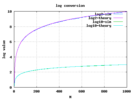
Simple Matlab/Octave script for computing the logarithm via the LUT based approach is provided. Click here to download Matlab/Octave script for performing linear to log conversion using LUT based approach

Figure: Linear to log conversion using LUT
Reference
DSP Trick: Quick-and-Dirty Logarithms – Ray Andraka, June 2000


i need help i have to builld an audio power meter, right am stuk i need a linear to logarithm converter circuit
@Sibo: Well, did the idea in this post help you?
@sandeep: Oh, yes 🙂 I corrected the equation in the post to j = (N/2^E -1)2^k.
Thanks for the close review.
Guess I was not clear. In your write-up you have written
j = (M/2^E -1)2^k. Agee? Now in Matlab code it is
j = (N/2^E -1)2^k. Agree? if yes then both doesnot match.
@sandeep: No, it is indeed M. The index j is used for finding only the mantissa part.
k need not be related to bitwidth of N. k just defines the depth of the LUT; higher the value of k, better the precision.
Makes sense?
Hi
Nice article..Some minor correction
In equation for j, there should N instead of M.
Also i think choice of k should be related to bit width of N. Have you defined it?
Regards
@vasundhara: Sorry, I do not have the source code. Typically I only try to help the reader to debug the model rather than writing the code myself. Kindly do email if you have explicit queries.
@Sky Stradlin: Thanks 🙂 Sure, do hope to run. btw, if you want to share your ideas/thoughts on the blog, you can email me.
man, your blog is really useful, please keep it running !
Cheers
please can you privide me a matlab source code?
IEEE TRANSACTIONS ON WIRELESS COMMUNICATIONS, VOL. 7, NO. 2, FEBRUARY 2008 495
Finger Assignment Schemes for RAKE Receivers with
Multiple-Way Soft Handover
Seyeong Choi, Member, IEEE, Mohamed-Slim Alouini, Senior Member, IEEE,
Khalid A. Qaraqe, Senior Member, IEEE, and Hong-Chuan Yang, Senior Member, IEEE
Abstract—We propose and analyze new finger assignment
techniques that are applicable for RAKE receivers in the soft
handover (SHO) region. Specifically, extending the results for the
case of two-base station (BS), we consider the multi-BS situation,
attack the statistics of several correlated generalized selection
combining (GSC) stages, and provide closed-form expressions for
the statistics of the output signal-to-noise ratio (SNR). By investigating
the tradeoff among the error performance, the average
number of required path estimations/comparisons, and the SHO
overhead, we show through numerical examples that the new
schemes offer commensurate performance in comparison with
more complicated GSC-based diversity systems while requiring
a smaller estimation load and SHO overhead.
Index Terms—Fading channels, diversity methods, RAKE
receiver, generalized selection combining (GSC), performance
analysis.