The post on MIMO with Zero Forcing equalizer discussed a probable way of equalizing a 2×2 MIMO channel. The simulated results with the 2×2 MIMO system with zero forcing equalizer showed matching results as obtained in for a 1×1 system for BPSK modulation in Rayleigh channel. In this post, we will try to improve the bit error rate performance by trying out Successive Interference Cancellation (SIC). We will assume that the channel is a flat fading Rayleigh multipath channel and the modulation is BPSK.
The background material on the MIMO channel has been described in the post on Zero Forcing equalizer. The text is repeated again for easy readability.
2×2 MIMO channel
In a 2×2 MIMO channel, probable usage of the available 2 transmit antennas can be as follows:
1. Consider that we have a transmission sequence, for example
2. In normal transmission, we will be sending in the first time slot,
in the second time slot,
and so on.
3. However, as we now have 2 transmit antennas, we may group the symbols into groups of two. In the first time slot, send and
from the first and second antenna. In second time slot, send
and
from the first and second antenna, send
and
in the third time slot and so on.
4. Notice that as we are grouping two symbols and sending them in one time slot, we need only time slots to complete the transmission – data rate is doubled ! 🙂
5. This forms the simple explanation of a probable MIMO transmission scheme with 2 transmit antennas and 2 receive antennas.
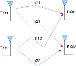
Figure: 2 Transmit 2 Receive (2×2) MIMO channel
Other Assumptions
1. The channel is flat fading – In simple terms, it means that the multipath channel has only one tap. So, the convolution operation reduces to a simple multiplication. For a more rigorous discussion on flat fading and frequency selective fading, may I urge you to review Chapter 15.3 Signal Time-Spreading from [DIGITAL COMMUNICATIONS: SKLAR]
2. The channel experience by each transmit antenna is independent from the channel experienced by other transmit antennas.
3. For the transmit antenna to
receive antenna, each transmitted symbol gets multiplied by a randomly varying complex number
. As the channel under consideration is a Rayleigh channel, the real and imaginary parts of
are Gaussian distributed having mean
and variance
.
4. The channel experienced between each transmit to the receive antenna is independent and randomly varying in time.
5. On the receive antenna, the noise has the Gaussian probability density function with
with
and
.
7. The channel is known at the receiver.
Zero forcing equalizer for 2×2 MIMO channel
Let us now try to understand the math for extracting the two symbols which interfered with each other. In the first time slot, the received signal on the first receive antenna is,
.
The received signal on the second receive antenna is,
.
where
,
are the received symbol on the first and second antenna respectively,
is the channel from
transmit antenna to
receive antenna,
is the channel from
transmit antenna to
receive antenna,
is the channel from
transmit antenna to
receive antenna,
is the channel from
transmit antenna to
receive antenna,
,
are the transmitted symbols and
is the noise on
receive antennas.
For convenience, the above equation can be represented in matrix notation as follows:
.
Equivalently,
To solve for , The Zero Forcing (ZF) linear detector for meeting this constraint
. is given by,
.
To do the Successive Interference Cancellation (SIC), the receiver needs to perform the following:
Zero Forcing with Successive Interference Cancellation (ZF-SIC)
Using the Zero Forcing (ZF) equalization approach described above, the receiver can obtain an estimate of the two transmitted symbols ,
, i.e.
.
Take one of the estimated symbols (for example ) and subtract its effect from the received vector
and
, i.e.
.
Expressing in matrix notation,
,
The above equation is same as equation obtained for receive diversity case. Optimal way of combining the information from multiple copies of the received symbols in receive diversity case is to apply Maximal Ratio Combining (MRC).
The equalized symbol is,
.
This forms the simple explanation for Zero Forcing Equalizer with Successive Interference Cancellation (ZF-SIC) approach.
Simulation Model
The Matlab/Octave script performs the following
(a) Generate random binary sequence of +1’s and -1’s.
(b) Group them into pair of two symbols and send two symbols in one time slot
(c) Multiply the symbols with the channel and then add white Gaussian noise.
(d) Equalize the received symbols with Zero Forcing criterion
(e) Take the symbol from the second spatial dimension, subtract from the received symbol
(f) Perform Maximal Ratio Combining for equalizing the new received symbol
(g) Perform hard decision decoding and count the bit errors
(h) Repeat for multiple values of and plot the simulation and theoretical results.
Click here to download Matlab/Octave script for simulating BER for BPSK modulation in 2×2 MIMO with Zero Forcing and Successive Interference Cancellation equalization (in Rayleigh channel)
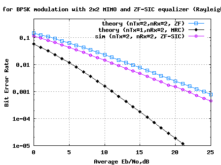
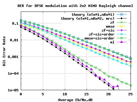
Figure: BER plot for BPSK in 2×2 MIMO channel with Zero Forcing Successive Interference Cancellation equalization
Observations
Compared to Zero Forcing equalization alone case, addition of successive interference cancellation results in around 2.2dB of improvement for BER of .
The improvement is brought in because decoding of the information from the first spatial dimension () has a lower error probability that the symbol transmitted from the second dimension. However, the assumption is that
is decoded correctly may not be true in general. We can discuss alternate approaches in future posts. 🙂
References
[DIG-COMM-BARRY-LEE-MESSERSCHMITT] Digital Communication: Third Edition, by John R. Barry, Edward A. Lee, David G. Messerschmitt
[WIRELESS-TSE, VISWANATH] Fundamentals of Wireless Communication, David Tse, Pramod Viswanath
Dear Krishna,
Can you guide me on the accuracy of the BER analysis based on the number of times the Monte Carlo simulations are run?
I want to know after how many Monte Carlos can I be sure that my BER graph is accurate for a Rayleigh Fading Channel
@Razi: Typically, one need to run the simulations sufficiently large number of times to ensure that the simulation results are accurate. When computing the bit error rate, one solution is to ensure that we have atleast 100 errors for each Eb/N0 point
i want matlab code of parellel interference cancellation and sic
@samyak: what is parallel interference cancellation? my understanding was that we estimate each symbol and remove then one after the other.
Hi krishna!
Excellent work.
I’m trying to implement physically a 2×2 MIMO system, do you think I would need to add something else (besides mixers, amplifiers and LNAs) that the code for the transmission and reception as used in matlab?
@Gidy: Multipath channel + equivalent model for all the receive blocks should typically suffice
No offence to the writer but i’ve already spotted like 2-3 typo’s and havent even finished reading lol — do they charge you for spellchecker in your time zone (just kidding) nice layout though I’ll give you that 🙂
@Murray Lefevers: Aaah… sorry for the typos. On hindsight, am not a good proof reader…have to improve on that
Hi krishna
I want to build simple 2×2 MIMO-CDMA system using 16-QAM and zero forcing detector in MATLAB. So please help….
@Siddappa: I have discussed MIMO BPSK with zero-forcing equalizer in one of the post
https://dsplog.com/2008/10/24/mimo-zero-forcing/
It should be straightforward to extend it to 16qam case
hi can u help me on interference cancellation on mimo
@krishna: Did this post help?
Hi Krishna Sankar,
Your article is great!
I am reading your code to more understand, so please help me:
Why to calculate the inverse matrix as in the source code rather than using “inv” and “transpose” code in Matlab?
% Inverse of a [2×2] matrix [a b; c d] = 1/(ad-bc)[d -b;-c a]
Tks!
2.
@Thanh: Wanted to vectorize the operations (i.e. without for loops) to make the execution fast in Matlab. Hence did not use inv()
hello sir,
is it possible that we use the ZF receiver with 2*1 ,and 1*2 antenna system.?
please guide me how is that possilbe?
@rinky: Some post on
a) 1 transmit antenna, 2 receive antenna
Maximal ratio combining (MRC) https://dsplog.com/2008/09/28/maximal-ratio-combining/
Equal gain combining https://dsplog.com/2008/09/19/equal-gain-combining/
Selection diversity https://dsplog.com/2008/09/06/receiver-diversity-selection-diversity/
b) 2 transmit antenna, 1 receive antenna
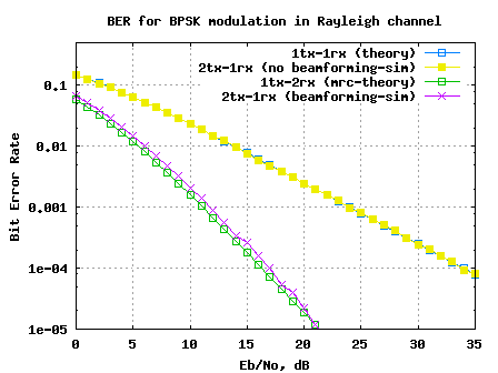
Transmit beamforming
https://dsplog.com/2009/04/13/transmit-beamforming/
matlab code interference cancellation in mimo
i nazia is working with interference cancellation in mimo i want matlab code parallel interference cancellation
@nazia: Hope this post helps.
noise cancellation mat lab code in mimo pl help me
i nazia want matlab code for interference cancellation using mimo system
i nazia parveen want matlab code for interference cancellation using mimo using parallel interference cancellation algorithm
i nazia working as professor is guiding project on interference cancellation using mimo please help me for code using v-blast
please Mr. Krishna Sankar Iwant to build simple mimo ofdm system to simulate snr vs. ber but I want it the mimo system to be flexable not only 2×2 so ican change the number of transmitter and recievers please help me if you have the matlab code please send it to me
@eng_dina: In most of the articles which I have discussed I have used 2×2 MIMO case. And to increase the speed of the Matlab simulations, I have not used inv() operation in Matlab. You can try using inv() operation and increase the speed of the simulations
hello,
with match respect can you mr send me a explain shéma of MMSE,ZF,ZF_SICand MMSE_SIC.
Thank you
@mannou: Plz refer https://dsplog.com/2009/04/21/six-equalizers-for-v-blast/
Hi,
Thanks for your high quality contribution in this site.Could you please mention some refernce books for understanding the theory what you have used here.
@Zakia: Some of the books which I refer are listed here
https://dsplog.com/2008/12/24/books/
I have done simulation with MMSE-SIC but there is no diversity gain compared with MMSE equalizer. I have tried to find out the reason but I haven’t got it. Would you please give me an explain. Thank you in advance
@minh: I have not compared MMSE-SRC vs MMSE. However, from my results comparing ZF-SIC vs ZF, I can see gains.
https://dsplog.com/2009/04/21/six-equalizers-for-v-blast/
Sorry, I found my mistake, MMSE-MRC is still better than MMSE . By the way, thank you so much for your post. It helps me a lot!
@minh: Glad to help.
what exactly is the meaning of successive interfernce cancellation?
when we subtract x2 from y1 to get x1,,, does this mean that we are cancelling noise common to both spatial stream?
thanks
@jhon: No, we form an estimate of one symbol. Then use that estimate to subtract the interference caused by that symbol to the other symbol.
hi krishna………hi sir…………
I am working multiuser detection successive interference cancellation with goldcode 31 but still error .can you help me?
emailme in yutt.pangestu@gmail.com. thanks…..
this the programs :
*main
clc,clear all;
format long;
SNR_dB=0:5:30;
P=[1 1 1 1 1];
Nb=10000;
squence=gold_codes;
chan_type=2;
BER_sic=sim_sic(SNR_dB, P, Nb, squence, chan_type)
semilogy(SNR_dB, BER_sic, ‘bv-‘)
xlabel(‘SNR dalam dB’);
ylabel(‘probabilitas bit error’);
grid;
legend(‘sic awgn’);
title(‘simulasi sic’);
hold on;
*sim_sic
% BER_sic=sim_sic_fn(SNR_dB, P, Nb, code_matrix, chan_type)
% return bit error rate of the sic receiver in AWGN or rayleigh fading
%
% PARAMETER:
% SNR_dB=signal-ti-nopise ratio in dB
% P=power control vector, P(i)=transmitted power of i-th user
% Nb=number of transmitted bit
% code_matrix=matrix of the spreading code used
% chan_type=channel type(1=AWGN, 2=rayleigh fading channel)
%
% output:
% BER_sic=bit error of the sic receiver
%
function BER_sic=sim_sic(SNR_dB, P, Nb, squence, chan_type)
BER_sic=zeros(size(SNR_dB));
K=length(P); %number of user
N=size(squence,2); %spreading factor
G(:,1)=squence(33,:)’;
G(:,2:K)=squence(1:K-1,:)’;
%generate the crosscorrelation matrix R
R=G’*G;
for p=1:length(SNR_dB),
SNR=10^(SNR_dB(p)/10);
SNRchip=SNR/N;
disp(‘processing…’)
error_count=0;
%loop for Nb symbol bits
for n=1:Nb,
%generate a bernoulli symbol, i.e. b=1 or 0
b=input_symbols(K,1);
if chan_type==1
A=sqrt(P’);
elseif chan_type==2
A=rayleigh(1,K).*sqrt(P’);
else
disp(‘invalid channel type’);
dbquit;
end
%transmitted sinal
X=G*(A.*b);
%generate the observed data
r=awgn_chan(x,SNRchip);
%assume that the codes are known and that they are
%perfectly synchronized
%matched filter output
y=G’*r;
%short users according tho their received powers
[y_sorted,sort_order]=sort(y.^2);
user_index=find(sort_order==1);
y_sorted=y(sort_order);
A_sorted=A(sort_order);
R_sorted=R(sort_order,sort_order);
%detect users successively
b_hat=zeros(K,1);
b_hat(K)=sign(y_sorted(K));
for u=K-1:-1:1,
b_hat(u)=sign(y_sorted(u)-sum(A_sorted(u+1:K).*R_sorted(u+1:K,u).*b_hat(u+1:K)));
end
b_hat(1)=sign(y_sorted(1)-interference_estimate(1));
%if detected symbol is incerrect, increment the error_count
if b_hat(user_index)~=b(1)
error_count=error_count+1;
end
end
%carculating Bit Error rate i.e. the percentage of erroneous
%symbol estimates
BER_sic(p)=error_count/Nb;
end
*awgn_chan
% r=awgn_chan(signal,SNR)
% return the awgn channel output given the input signal and the SNR
%
% PARAMETERS:
% Vsignal=normalized anti podal signal (-1,+1); can be a matrix
% SNR=linear signal-to-noise ratio for the AWGN channel
%
% OUTPUT:
% r=AWGN channel output
%
function r=awgn_chan(signal,SNR)
sigma=1/sqrt(SNR);
r=signal+sigma*randn(size(signal));
*rayleigh
% A=rayleigh(omega,K)
% return a vector of rayleigh-distrimuted random variables
%
% PARAMETERS:
% omega=variance of the rayleigh-distributed random variables
% K=length of vector (i.e. number of users)
%
% OUTPUT:
% A=vector of rayleigh-distributed RVS
%
function A=rayleigh(omega,K)
A=sqrt(omega*log(1./(1-rand(K,1))));
*input_symbols
% b=input_symbols(K,Nb)
% Return the randomly generated antipodal symbol(+1,-1)
%
% PARAMETERS:
% K=number of users
% Nb=number of symbol for each user
%
% OUTPUT:
% b=the randomly generated antipodal symbols
%
function b=input_symbols(K,Nb)
b=sign(rand(K,Nb)-0.5);
*gold_codes
function [gold_codes]=gold_codes
clc;
Xa=[0 0 0 1 0];
Xb=[0 0 0 1 0];
t=1:1:31;
for i=1:31
Xa=[mod(Xa(3)+Xa(5),2) Xa(1:4)];
seq1(i)=Xa(5),
Xb=[mod(Xb(2)+Xb(4)+Xb(5),2) Xb(1:4)];
seq2(i)=Xb(5),
gold_codes(i)=mod(Xa(5)+Xb(5),2);
end
thanks………
@ w@p: Sorry, due to time constraints, may I refuse to debug the code
hi good work thank u
i want to ask if we used alamouti code and we want to do the mmse-sic reciever
what will be different than the above algorithm?
thx in advance
@mohamed: Well, with Alamouti coding we do not need MMSE-SIC receiver. A Zero Forcing equalization is optimal.
Hi,
Iwould like knowing if we can use VBLAST with multiuser(CDMA).If yes you can send me a code matlab for that.Think you.
@samira: The modeling of V-BLAST and multiuser communication is kind of similar (in V-BLAST the other spatial stream is the interferer and in multiuser the other user is the interferer). I did not quite understand your intention, when you said you want to put together V-BLAST with multi user.
Hi Krishna
This is very useful site,keep it up, do u have any MATLAB code for multicarrier delay diversity moduulation(MDDM)for MIMO
@shah: Thanks.
No, I have not tried modeling multi carrier delay diversity modulation.
Hello Krishna, can you start tutorials for multiuser detection for cdma and ofdma. Thanks
@Communications_engineer: Sure. Further, the articles of receiver structures for V-BLAST can be directly applied to Multi user detection case too. Agree?
Hi Sir,
I am doing work on wireless communication.would like to send me a matlab code for frequency modulation (BW=200 kHz).
2- how to plot the spectrum of it?
Thanks
kind regard
@tidjani: Sorry, I have not written posts on FM modulation.
Can u give me some explain on the H^H operation in your Matlab script?
@Ronaldo: ()^H is the Hermitian operator. Hermitian operator means – conjgutate transpose of a matrix
hi, the ZF-SIC should be a non-linear approach, but why the result you got is so linear?
@John: Hmm… I did not follow your question. As the SNR increases, its reasonable to expect lower BER too….
hi krishna
what about golden code? whether there r any posts about MIMO using golden codes?
@darshini: No, nothing yet on golden codes with MIMO
hi krishna
thanks, ur alamouti code helped me. But in that URL u give for v-blast, i cant find any specific v-blast codings. All are with ZF,SIC etc.. except v-blast. can u plz let me know…In v-blast processing steps there shld be a optimal ordering step, but here mimo with zf and optimal ordering is available. whether it is v-blast or any specific v-blast coding is available?
@darshini: As I understand, in V-Blast we transmit the different symbol simultaneously from two tx antennas. Whether we do optimal ordering for decoding is receiver dependent. The simplest equalization scheme uses Zero Forcing, and then we can have decoding schemes like MMSE, MMSE-SIC, ML etc.
hi
I am working on BER performance of MIMO with V-BLAST spatial multiplexing and space time codes like golden code, almouti code, linear dispersion code etc. Can u provide me the simulation code, if u tried for any of the above(especially v-blast).
hi
I am working on BER performance of MIMO with V-BLAST spatial multiplexing and space time codes like golden codes, almouti code and linear dispersion codes
can u provide me the simulation code if u tried for any of above.
@darshini: I have some posts on MIMO V-BLAST at
URI: https://dsplog.com/tag/mimo/
There is also a post on Alamouti STBC code @
https://dsplog.com/2008/10/16/alamouti-stbc/
Hope this helps.
can find me code with mimi vblast
@moh: You meant, MIMO with V-BLAST. This post indeed talks about V-BLAST scheme. For MIMO V-BLAST with zero forcing equalizer, please refer to
https://dsplog.com/2008/10/24/mimo-zero-forcing/
Hope this helps.
@karl: Thanks 🙂 Sure, will add posts on MIMO-OFDM.
great work Krishna. congrats. your coding style is simple and easy to understand. hope you can post some work about MIMO-OFDM for example using alamouti or CDD. keep posting.