The post on thermal noise described the noise produced by resistor ohms over bandwidth
at temperature
Kelvin. In this post, let us define the noise voltage at the input and output of a resistor network and further use it to define the Noise Figure of such a network.
From Section 2.3.2 of RF Microelectronics, Behzad Razavi, the noise figure is defined as
, where
is the input signal to noise ratio and
is the output signal to noise ratio.
Note : Some textbooks refer to this term as Noise Factor.
Noise Figure of a resistor network
Consider a simple resistor circuit with as the input voltage,
source resistance and
as the parallel resistance (shown below) :
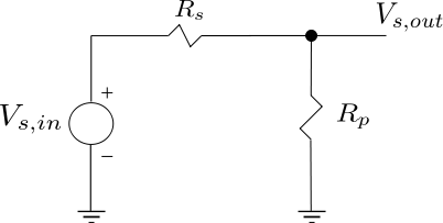
Figure : Resistor network (Reference : Figure 2.30(a) of RF Microelectronics, Behzad Razavi)
The noise voltage due to the source resistance is
.
The Signal to Noise Ratio at the input is,
.
The signal voltage at the output is,
The noise voltage at the output is,
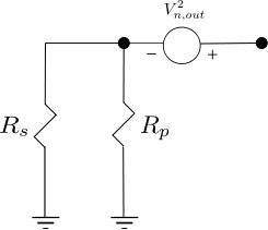
Figure : Equivalent resistor noise model for two parallel resistor (Reference : Figure 2.30(b) of RF Microelectronics, Behzad Razavi)
.
The Signal to Noise Ratio at the output is,
.
Calculating,
.
The Noise Figure is,
Observations
a) Per the Maximum Power Transfer theorem the source and load resistance should be equal i.e . However that condition does not coincide with the minimum noise figure. The source and load resistance and equal results in
(3dB in decibels)
b) Noise Figure is minimized by maximizing resistance OR minimizing source resistance
.

Amazing!!!You not only good in communication and DSP field, but also interest in RF area, thank you!!!