My friend and colleague Mr. Vineet Srivastava pointed me to a nice article on clock jitter – Clock Jitter Effects on Sampling : A tutorial – by Carlos Azeredo-Leme, IEEE Circuits and Systems Magazine, Third Quarter 2011. In this post, let us discuss the total Signal to Noise Ratio at the output of an analog to digital converter (ADC) accounting for errors due to sampling clock jitter and quantization noise.
Clock jitter
The error in the sampling clock results in an error in the sampled voltage as show in the figure below. Can see that the jitter in the clock results in an error voltage
.
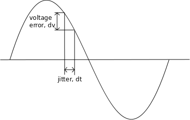
Figure : Voltage error caused by jitter
For a signal ,
the ratio of the voltage error and the time delta
is the slope i.e.
.
Re-ordering, and replacing with the error voltage
,
Taking the mean square error,
where
is the variance of the clock jitter.
The signal to noise ratio at the output of ADC due to jitter alone is,
.
Assuming that the signal is sinusoidal, i.e.
.
The first derivative is,
The signal power is,
The error power is,
The signal to noise ratio is,
.
Expressing in decibels,
Quantization Noise
An input signal with swing from of
volts will get discretized by an
bit ADC to
levels.
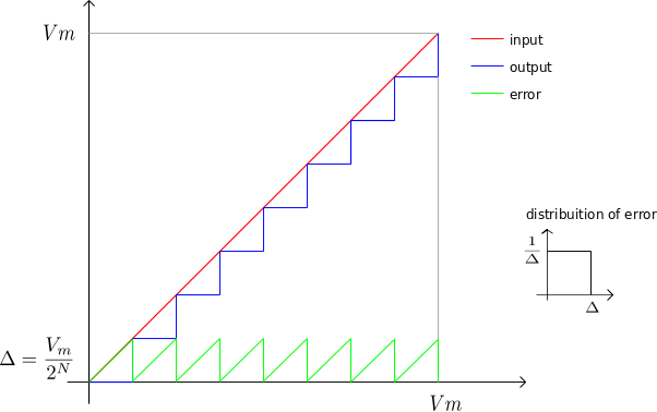
Figure : Input and output from an N bit ADC (with N=3)
The maximum error is .
For a linearly varying input as show above, the error voltage is having a uniform distribution
.
The error voltage is a periodic repetition of the sawtooth waveform,
The power of the error signal is,
.
For an input sinusoidal signal ,the signal power is,
.
The signal to quantization noise ratio is,
Expressing in decibels,
.
Total Signal to Noise Ratio
The overall signal to noise ratio for an ADC with both quantization noise and jitter is,
The simple Matlab script computes the total SNR for 10bit ADC with varying input frequency for different rms jitter specifications.
clear all; close all;
fs_MHz 	= 2000;  % sampling clock
fm_MHz 	= [0.1:1:1000]; % signal frequency
t_rms_ps= [5 10 20 50 100]; % rms jitter
tn 	= [0:1/fs_MHz:10];
nBit	= 10; % number of bits of the ADC
snr_dB  = zeros(length(t_rms_ps),length(fm_MHz));
for (jj = 1:length(t_rms_ps))
	tn_jitter	= tn + t_rms_ps(jj)*1e-6*randn(size(tn));
	for (ii = 1:length(fm_MHz))
		xt = (exp(j*2*pi*fm_MHz(ii)*tn));
		yt = (exp(j*2*pi*fm_MHz(ii)*tn_jitter));
		yt = floor(yt*2^(nBit))./2^(nBit);
		err = yt - xt;
		sig_pwr = xt*xt'/length(xt);
		err_pwr = err*err'/length(err);
		snr_dB(jj,ii) = 10*log10(sig_pwr/err_pwr);
	end
end
semilogx(fm_MHz,snr_dB.');
grid on;axis([0.1 1000 20 70]);
xlabel('freq MHz'); ylabel('SNR, dB');
legend('5ps','10ps','20ps','50ps','100ps');
title('SNR for 10bit ADC with different RMS jitter values');
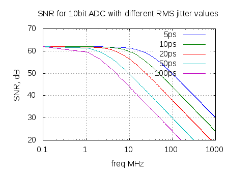
Figure : Total SNR for a 10bit ADC with different RMS jitter specifications (simulation of the Figure 3 in Clock Jitter Effects on Sampling : A tutorial)
Observations
a) For lower frequency signals, quantization error dominates.
b) For higher frequency signals, the jitter error dominates.
References
Little Known Characteristics of Phase Noise by Paul Smith, Analog Devices Application Note, AN-741

One thought on “ADC SNR with clock jitter and quantization noise”