The earlier posts on phase noise discussed about phase noise in oscillators, conversion of phase noise profile to jitter and the impact of phase noise on the error vector magnitude (evm). This post discuss the impact of phase noise on the spectrum of the transmit waveform. A simple random QPSK modulated symbols, oversampled and passed through a root raised cosine filtering is used for the simulation.
System Model
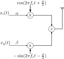
Consider a simple system model having both phase noise and thermal noise as show below. 
Figure: System model with phase and thermal noise
The received symbol is,
, where
is the phase distortion in radians,
is the transmit symbol and
is the contribution due to thermal noise The phase
is Gaussian distributed with zero mean and variance
radians^2 having a probability density function as,
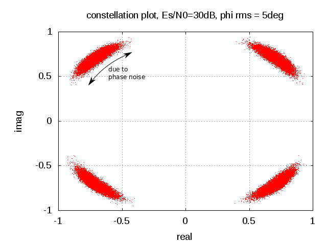
. From the post on phase noise on the error vector magnitude (evm), we know that the
Es/N0 = 40dB
| Phase Noise (deg, rms) | EVM, dB |
| 0 | -40.00 |
| 1 | -33.93 |
| 2 | -28.80 |
| 3 | -25.46 |
| 4 | -23.03 |
| 5 | -21.13 |
Table : Resultant EVM with phase noise and thermal noise
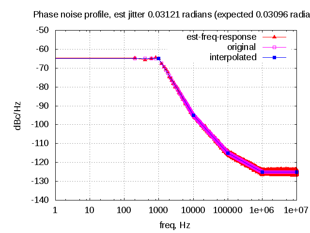
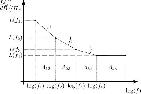
Further, from the post on phase noise in oscillators, it is also known that the phase noise will cause skirts in the spectrum of the carrier.

Figure : Spectrum on the transmit waveform with random QPSK symbols, root raised cosine filtering (oversampling by 4), Es/N0 = 40dB and different RMS phase noise. ObservationsAs can be seen from the above plot, the phase noise elevates the out-of band emissions in the transmit spectrum (from -40dB in the no phase noise case to -21.13dB for the 5 degree rms phase) So it is important to have a lower phase noise to meet the spectral mask specification in addition to minimize the impact on error vector magnitude.
Matlab/Octave code
Attached script computes the transmit spectrum of a QPSK modulated symbol versus Es/N0 for different values of rms phase noise.
% Script for simulating the transmit spectrum of a QPSK
% modulated symbol affected by phase noise and thermal noise
% ----------------------------------------------------------

clear;close all;
N = 10^5; % number of symbols
os = 4; % oversampling factor

Es_N0_dB = 40;
phi_rms_deg_vec = [0:1:5];

% root raised cosine filter
t_by_Ts = [-4:1/os:4];
beta = 0.5;
ht = (sin(pi*t_by_Ts*(1-beta)) + 4*beta*t_by_Ts.*cos(pi*t_by_Ts*(1+beta)))./(pi*t_by_Ts.*(1-(4*beta*t_by_Ts).^2));
ht((length(t_by_Ts)-1)/2+1) = 1 -beta + 4*beta/pi;
ht([-os/(4*beta) os/(4*beta)]+(length(t_by_Ts)-1)/2+1) = beta/sqrt(2)*((1+2/pi)*sin(pi/(4*beta))+(1-2/pi)*cos(pi/(4*beta)));
ht = ht/sqrt(os);

for ii = 1:length(Es_N0_dB)
	for jj = 1:length(phi_rms_deg_vec)

	   % Transmitter
	   ip_re = rand(1,N)>0.5; % generating 0,1 with equal probability
	   ip_im = rand(1,N)>0.5; % generating 0,1 with equal probability
	   s = 1/sqrt(2)*(2*ip_re-1 + j*(2*ip_im-1)); % QPSK modulation

	   % Pulse shaping
	   s_os = [s ; zeros(os-1,length(s))];
	   s_os = s_os(:).';
	   s_os = conv(ht,s_os);
	   s_os = s_os(1:os*N);

	   % Thermal and Phase Noise addition
	   n = 1/sqrt(2)*[randn(1,N*os) + j*randn(1,N*os)]; % thermal noise
	   phi = phi_rms_deg_vec(jj)*(pi/180)*randn(1,N*os)*sqrt(os); % phase noise
	   y = s_os.*exp(j*phi) + 10^(-Es_N0_dB(ii)/20)*n;

	   % computing the transmit spectrum
	   [Pxx1(jj,:) W2 ] = pwelch(y,[],[],1024,'twosided');

	   % matched filtering
	   y_mf_out = conv(y,fliplr(ht));
	   y_mf_out = y_mf_out(length(ht):os:end);

	   % error vector
	   error_vec = (y_mf_out-s);
	   evm(ii,jj)  = error_vec*error_vec';
	   theory_evm(ii,jj) =  10^(-Es_N0_dB(ii)/10) + 2 - 2*exp(-(phi_rms_deg_vec(jj)*pi/180).^2/2);

	end
end

figure;
plot([-512:511]/1024,10*log10(fftshift(Pxx1)));
xlabel('frequency, Hz'); ylabel('amplitude, dB');
legend('0 deg rms','1 deg rms', '2 deg rms', '3 deg rms', '4 deg rms', '5 deg rms');
title('spectrum Es/N0 = 40dB, root raised cosine filtering and different rms phase noise');
axis([-0.5 0.5 -50 5]); grid on;